Peter Knott
Newbie level 3
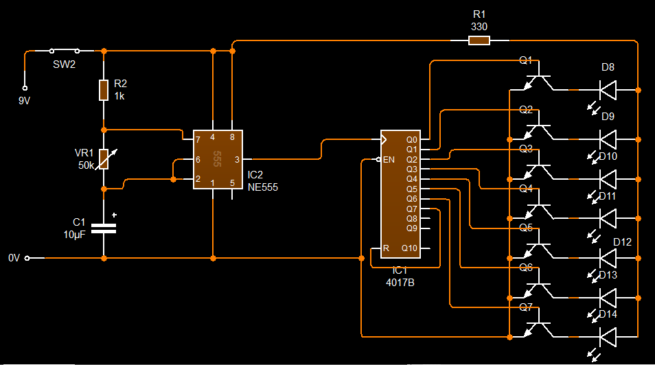
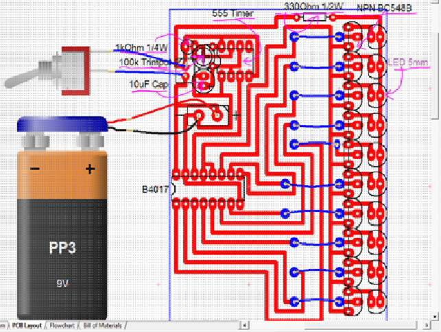
Hey Guys, I have a few question relating to my chasing led circuit but before i get into that I'll explain a bit. The aim of this circuit is to have 10 LED go on and off right after each other giving of the illusion that the LEDs are chasing each other.
MY QUESTIONS
1) Looking at my design would any component values need to be changed?
2) Do resistors lower the current or just the voltage?
3) How can I modify this circuit to make all the LEDs light up at the same time and stay that way as well as the chasing LED option?
Cheers in advance")
MY QUESTIONS
1) Looking at my design would any component values need to be changed?
2) Do resistors lower the current or just the voltage?
3) How can I modify this circuit to make all the LEDs light up at the same time and stay that way as well as the chasing LED option?
Cheers in advance
Last edited by a moderator: