Continue to Site

Welcome to EDAboard.com

Welcome to our site! EDAboard.com is an international Electronics Discussion Forum focused on EDA software, circuits, schematics, books, theory, papers, asic, pld, 8051, DSP, Network, RF, Analog Design, PCB, Service Manuals... and a whole lot more! To participate you need to register. Registration is free. Click here to register now.

[SOLVED] How many LEDS Off a 555

Status
Not open for further replies.
Still not working? Something is fundamentally wrong with your understanding of transistors. Connecting a CMOS directly to Vbe shorts the output to 1 diode drop, so that it cannot satisfy internal logic levels to toggle. The CMOS output voltage must be within valid logic levels. THe transistor with grounded emitter must not overload the CMOS output, so a suitable series Rbase is expected.

If you dont understand valid logic levels for CMOS yet, read , then ask. Same with transistor input impedance estimates, read or ask.
 

Well i have it working now but i need to work out the correct emmiter resistor, its 1 K or less for sure.

This is a good way of learning because i can see my mistakes and learn from them, yes maybe i need to read and learn/understand more but if i build this circuit, i can pat myself on my back and thank the great people on this forum for helping me out too (Spread the Love ;-).

102 posts (SORRY)

Going to be fun putting it to vero board :p
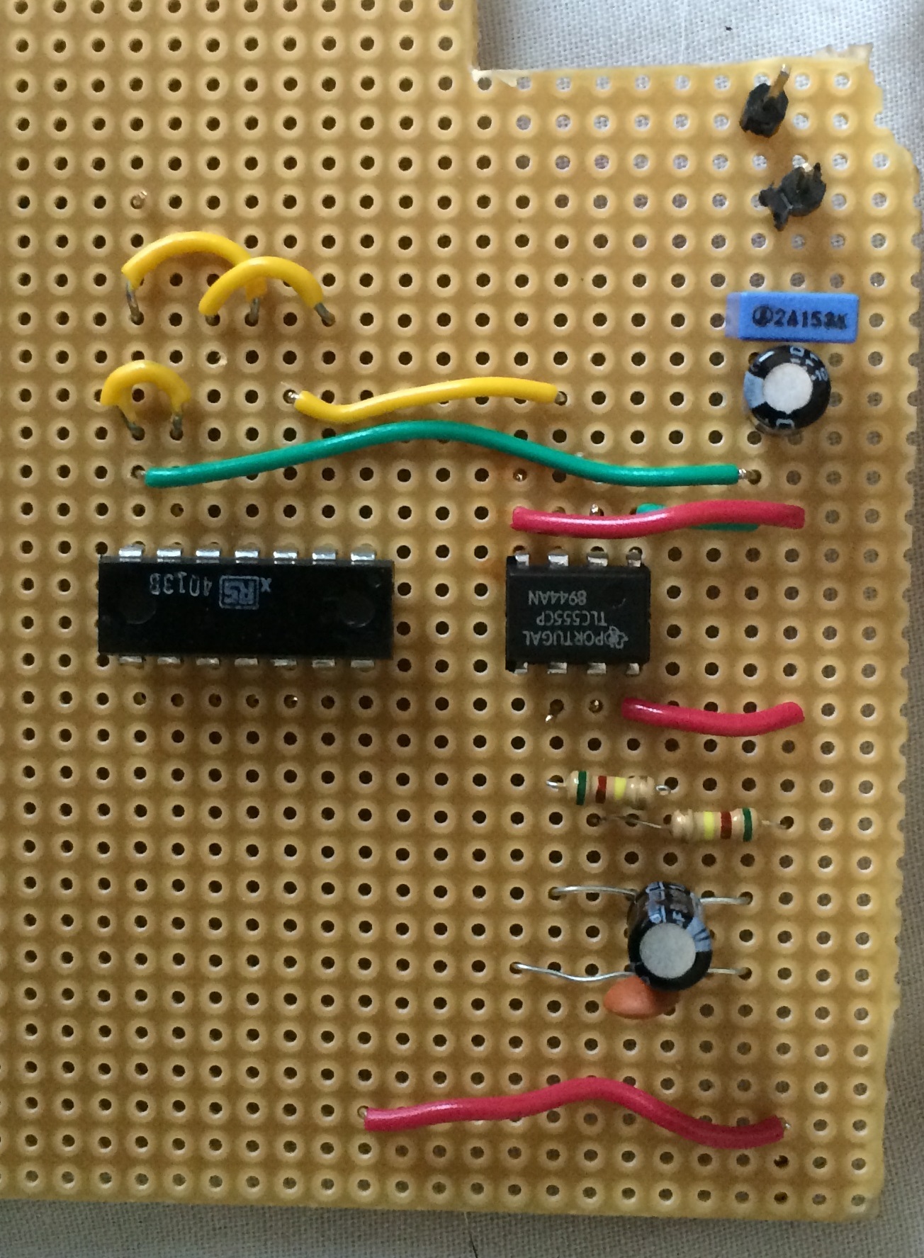
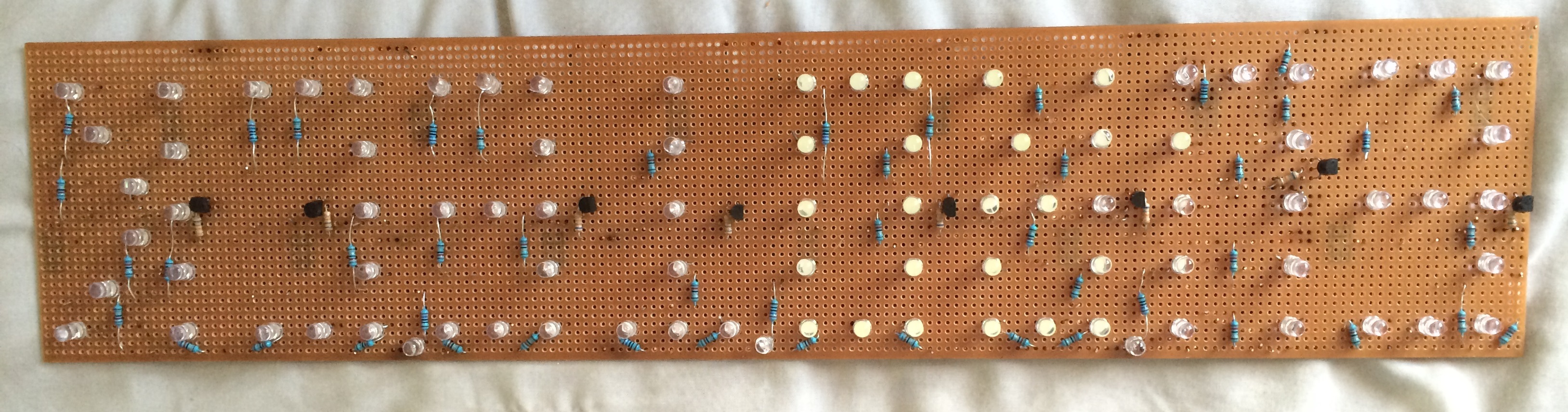
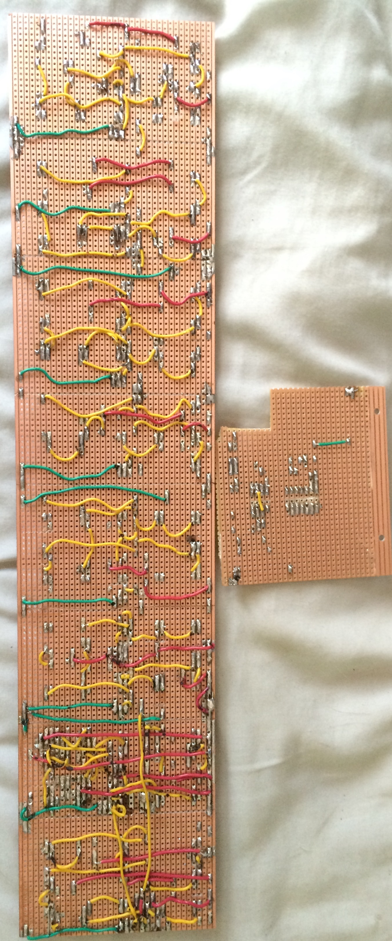
. Hahaha (Oh i can solder), so there wil be no soldering questions.

- - - Updated - - -

Strange!!.

Ive put 2 10 ohm resistors from emmiter to ground, i tried 1K the LEDs didnt light up - The LEDs stay on one transistor but doesnt change to the next colour. Stuck on Q NOT

If i remove the D link it flashes between the two colours but a different times - i presume this is because its floating IE- not connected.

- - - Updated - - -

The LEDS light up fine nice and bright, i just cant get the darn thing to flash inbetween the two colours.

Either stays on white or blue.

This is the last stage :-(.
 
Last edited:

You DO NOT NEED an emitter resistor. Your last schematic was fine with each darlington having a 68k resistor in series with its base and its emitter at 0V. Then the output of the CD4013 is not shorted almost to 0V by the base-emitter diodes in the darlingtons and the CD4013 can easily drive a few 68k resistors.
 

You should study relevant parts of this until you understand it.

To achieve a saturated switch of Ic/Ib=10 current ratio typical,
When both Rb and Rc go to the same voltage, the Rb/Rc ratio=10 and the Vce(sat) is given in the datasheet.

A better transistor might be rated for 20 to 50 when saturated and is a standard test method if capable.
A good Darlington is 1000:1 ratio minimum for Ic/Ib and the datasheet will give the details.

Remember that 5mm LED's when saturated have an effective series resistance of ~15 Ohms.

https://www.electronics-tutorials.ws/transistor/tran_4.html
 

Oaky.

1: Each transistor is going to ground without a resistor.
2: Q is going to the base of one transitor
3: Q NOT is going to the base of another transistor
4: Q NOT is connected to D
5: 555 Timer is connected to Clock
6: Reset & Set to ground (LOW)

If i have both transistors to ground, Q NOT output stays high and Q stays low.
If i only have Q NOT transistor to ground output stays high.
If i only have Q to ground Q flashes off and on.

The only way i can get them to flash between the two is by leaving D floating but thats a NO NO.

Thank you SunnyGuy i have read some of that previously obviously i need to read more!!!.

Do i need decoupling caps on the 4013?

Not very neat at the moment

image.jpg
 
Last edited:

The contact strips on your breadboard are SHORT-CIRCUITING both 68k base resistors!
Look at your schematic again. The 68k resistors are supposed to be series between the CD4013 Q and Q-not outputs to the darlington bases so that the CD4013 outputs are not shorted to almost 0V. Again, you might have destroyed the outputs of the CD4013.

Solderless breadboards are a tangle of long wires all over the place. Each long wire has inductance that messes up ICs then a decoupling capacitor is needed directly at the power supply pins of each IC. ICs on a printed circuit board or on a properly layed out stripboard are close together and have closeby power so only one decoupling capacitor is good for most ICs on a pcb. Since your circuit slowly blinks LEDs then there is plenty of time for IC inputs and outputs to stabilize which will not happen at high frequencies on a solderless breadboard that is missing some decoupling caps.

EDIT: The tutorial is wrong!. A transistor is not saturated when its base current is its collector current divided by its hFE (current gain). Sunny is correct when he says that for a transistor to be saturated then its base current should be about 1/10th its collector current as shown on most datasheets. hFE is used only when there is plenty of collector-emitter voltage so that the transistor is linear and is not saturated. The BC517 darlington has a minimum hFE of 30000 when its collector is 2V or more. But it is saturated when its base current is 1/1000th its collector current.
 
Last edited:
You should study relevant parts of this until you understand it.

To achieve a saturated switch of Ic/Ib=10 current ratio typical,
When both Rb and Rc go to the same voltage, the Rb/Rc ratio=10 and the Vce(sat) is given in the datasheet.

A better transistor might be rated for 20 to 50 when saturated and is a standard test method if capable.
A good Darlington is 1000:1 ratio minimum for Ic/Ib and the datasheet will give the details.

Remember that 5mm LED's when saturated have an effective series resistance of ESR(led)~15 Ohms.

https://www.electronics-tutorials.ws/transistor/tran_4.html
You said...
2: Q is going to the base of one transitor
3: Q NOT is going to the base of another transistor
THis is wrong. If you use a single transistor, Rb must be at least 10x Rc
To limit LED current to 20mA if Vf is somewhere around 3V from a 5V supply ( depends on colour and part number and ESR of LED) 2V drop on Rc for 20mA is Rc=100 Ohms, thus the collector load is 100+15 Ohms = 115 Ohms so Rb can be less than 10x if it does not load down the 300 Ohm output impedance of CD4xxx too much, but no more than (20x) for each transistor to guarantee transistor saturation. Thus Rb= 1150 or perhaps from 1k to 2k.

If you use a Darlington, Rb can be 1000x collector load =115 Ohms with a wider tolerance but the Darlington has an extra diode (Vsat=1V depending on current)) so the current limiting R reduces to 5V-3V-1V= 1V and at 20mA,= Rc= 50 Ohms
Thus Rb for the Darlington is around 1000x 50+15 =65k ( or closest value) for Rc= 50 Ohms.
Then Vout on Q will be near 5V and it will work.
 
Okay.

"68K are supposed to be in series :-S."

Ive noticed ive put the output of the CD4013 and the resitor in the same line.

So i should be using decoupling caps.

Im using a 68K resistor for Rb, so i need to put a 50 ohmat the collector.

You guy really do know your stuff.

- - - Updated - - -

That 50 OHM resistor sorted it out i think :).

Flashes well :)

Plus ive not got output and the resistor in the same line on the breadboard
 

I am glad that you noticed that the 68k series base resistors were shorted on the breadboard.

Sunny calculated 50 ohms for one 3.0V LED with a 5V supply. You do not have that. We calculated that 82 ohms limits the current in two series 3.2V LEDs to (8V - 6.4V)/82 ohms= 19.5mA which is close to the standard 20mA that all 5mm LEDs are spec'd at. If you use the non-standard value of 50 ohms then the current will be too high at 32mA and the LEDs might die in a few days.
 

Will i need to place a diode anywhere to protect the circuit?.

The LEDs dont seem to light up correct without the 50 OHM res

- - - Updated - - -

Actually, there fine with or with out resistors.
 
Last edited:

I think your last schematic was such a long time ago that it had a CD4017, not a CD4013. They both have the same output voltage and current and the base resistor was 68k and the series current-limiting resistor for the two series 3.2V LEDs was 82 ohms for 19.5mA of current.
 

Thank you, to everyone who helped me with the little circut.

It was my first circuit build and schematic, i know i kept asking questions after questions, i was just trying to get a better understaning of it all.

Hopefully i will be able to transfer it to veroboard and show you it working :).
 

The transfer from breadboard to veroboard is going very well, all of the letters are almost done now and working :).

Im going to need a 9V mains supply and im unsure of the current rating, i have a few old 9V plugs lying around off various electrical items.

They are rated 9V - 2A, 9V -500mA or i can buy one,

I have 8 1A transitors
1 555 timer (200mA)
1 4013 (Unsure)

Im unsure how to work out the current rating. (Sorry)
 

Calculate the current using simple arithmetic:
With a 9V supply and darlington driver transistors that have a 1V drop, each string of two series 3.2V LEDs in series with a 82 ohm current-limiting resistor draws a current of (9V - 1V - 3.2V - 3.2V)/82 ohms= 19.5mA.
How many strings will be lighted at the same time? The word EURO uses 24 strings and the word TECH also uses 24 strings. The LED powered by 9V uses 21mA and the 555 uses 6mA. The CD4013 uses almost no current. So the 9V power supply must supply a current of (19.5mA x 24) + 21mA + 6mA= 495mA. The 9VDC power supply might get pretty hot with 495mA but try it to see.
 
Cheers, I assumed this but I wasn't too sure.

Could I use a 1A power supply, or is this too much, i understand that the current is limited in the circuit by the resistors to protect the Components.
 

The battery in my car can supply 500A to start a freezing engine that has cold very thick oil in the winter. But does the clock in the car draw the entire 500A all the time or does it draw only the 5mA (0.005A) it was designed to use?
For your project, a 1A power supply will be fine and will get warm, not hot.
 

It will only draw the mA it was designed for.

I guess a fuse can be used between a high current power supply and a low current circuit then the fuse can blow before taking any thing else out.

It's all starting to make sense :).
 

Well, I have made it :).

All works fine too.

Took me awhile to do the letters as I kept checking each string of LEDS would light up, the back of the board looks like spaghetti but it works :)

A little video at the end.


Last edited:

Congratulations. It looks good and works well. Your soldering also looks good.
When I make a stripboard circuit, I put all the wire jumpers on the components side.
 

A couple of LEDS seem to go faulty, must be cheap LEDS.

I've enjoyed this project and learnt a lot, yes 6 pages later but I'm very grateful of the help.
 

Status
Not open for further replies.

Part and Inventory Search

Welcome to EDABoard.com

Sponsor

Back
Top