Continue to Site

Welcome to EDAboard.com

Welcome to our site! EDAboard.com is an international Electronics Discussion Forum focused on EDA software, circuits, schematics, books, theory, papers, asic, pld, 8051, DSP, Network, RF, Analog Design, PCB, Service Manuals... and a whole lot more! To participate you need to register. Registration is free. Click here to register now.

[AVR] How to map COM & segment terminals of segment LCD in order to display 0-9 numbers?

Status
Not open for further replies.

Mandar Joshi

Member level 2
Joined
Mar 4, 2015
Messages
50
Helped
0
Reputation
0
Reaction score
0
Trophy points
6
Activity points
445
How to map COM & segment terminals of segment LCD in order to display 0-9 numbers?

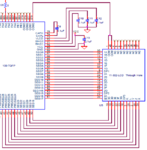
I have interfaced ATxmega64B1 with segment LCD(VI-302-DP-FC-S-LV) having 29 segments and 2 COM pins.


As the XMEGA manual says, the LCD controller can automatically handle ASCII characters. Instead of setting and clearing segments of the digit, the user enters the ASCII code and the Digit Decoder updates itself the corresponding segment values in the Display Memory. And for that four types of ASCII character mapping is supported, which includes

1. 3 COM term and 3 SEG term

2. 4 COM term and 2 SEG term

3. 4 COM term and 4 SEG term

4. 3 COM term and 6 SEG term


But my LCD is having only 2 COM terminals. So in order to display the numbers from 0-9 do I need to write corresponding look-up table for every digit as we do in Seven Segment Display or do I need to write the corresponding ASCII code for number?


Also, register CTRLG in LCD module contains the bit fields which specify Type of Digit and Start Segment what combination of these bit fields should I write for my display?


Do I need to use DECODE[6:0] bit field in CTRLH register to mention particular display pattern every time?


What are the pixel calculations in Data register in LCD module?


The LCD schematic is as follows. Rest of controller side pins for LCD are unconnected(i.e. used as GPIO as given in datasheet).
Schematic.PNG
 

Re: How to map COM & segment terminals of segment LCD in order to display 0-9 numbers

To start your project you'll read the LCD display datasheet to understand what type of LCD is it.

Doing so, you'll realize that it's a non-multplexed ("static") LCD with a single backplane COM terminal. Pin 1 and 40 have to bridged externally. ATxmega64B1 does support static LCD drive, but apparently no specific character mapping for it. In case of doubt, you'll perform the seven segment decoding in software.
 
Re: How to map COM & segment terminals of segment LCD in order to display 0-9 numbers

First of all thanks for quick reply.
So as you said in my case I need to write look-up table for all digit patterns.
But the CTRLG register in Xmega which includes bit fields for Type of Digits and Start Segment. What should I write for those bit fields as my LCD has only 2 COM terminals. Also in order to display those values do I need to write CTRLH or DATA register every time?
 

Re: How to map COM & segment terminals of segment LCD in order to display 0-9 numbers

You still didn't read the data sheet. Your LCD has functionally one not two two COM terminals, they have to be connected together to one COM driver pin.

Unfortunately I can't tell you how each register has to be setup for driving a static LCD.
 
Re: How to map COM & segment terminals of segment LCD in order to display 0-9 numbers

I did the change as you said in COM terminals connection. Actually I just want to know how to do those pixel calculations for DATA register of LCD, I can set the values for rest of registers.
 

Re: How to map COM & segment terminals of segment LCD in order to display 0-9 numbers

Hope its better to use old thread as related to same topic. I am having Xmega-B1 Xplained (ATXMEGA128B1 as main controller) board. In the datasheet of controller for LCD module there are some calculations regarding writing DATA register of LCD. They are as below:
lcd.png
Can someone tell me what are those formulas? How I need to use both the two formulas to put ON particular segment on LCD. I have tried it many ways but not getting at all. Any help is appreciated.
 

Re: How to map COM & segment terminals of segment LCD in order to display 0-9 numbers

Right decision to continue the previous thread.

As far as I understand, the used segments are simply assigned bottom up in the static drive scheme, in other words your segments 0 to 28 simply correspond to pixel 0 to 28 in the LCD data memory.

It's presumed that you set up everything for static drive and correct the post #1 schematic respectively. I read the datasheet so that there's no built-in 7-segment digit decoder available in static mode, you have to decode numbers to 7-segment in software. That's necessary anyway for an arbitrary segment wiring as in the post #1 schematic.

But before you design the decoder part, you should verify that you have set up the hardware correctly and can control individual segments on and off.
 

Re: How to map COM & segment terminals of segment LCD in order to display 0-9 numbers

First want to clear few things. There are CTRLG & CTRLH registers which can be used for displaying data on LCD or one can use DATA register to ON & OFF LCD segments individually.
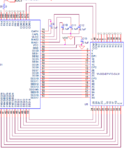
The schematic mentioned in #1 is for my final board, as you said for that LCD there is no built in 7-segment decoder I cannot use CTRLG or CTRLH register for LCD on my final board. I have modified my schematic in #1. Below is the modified one.
Final LCD Schm.PNG
So only option remains is DATA register. Now until I receive my final board I am trying same method on XMEGA-B1 Xplained board. For that I have written code for LCD initialization and all. There is one ready code available for this board https://eewiki.net/display/microcontroller/Basic+LCD+Example+for+Xmega-B1
In that link there is downloadable code for LCD which contains one function for displaying data using DATA register. It is as given below.
Code:
void lcd_set_pixel(uint8_t pix_com, uint8_t pix_seg) 
{
	if ((pix_com < LCD_MAX_NR_OF_COM) && (pix_seg < LCD_MAX_NBR_OF_SEG)) 
	{
		register8_t *pixreg = (register8_t *)((uint16_t)&LCD.DATA0)
		+ (pix_com * ((LCD_MAX_NBR_OF_SEG + 7) / 8))
		+ (pix_seg / 8);

		*pixreg |= 1 << (pix_seg % 8);
	}
}

I am just trying to relate above formulas with this function. But finding it bit difficult. Once I do this on evaluation board it will be easier for me to do on my final board.
 

Re: How to map COM & segment terminals of segment LCD in order to display 0-9 numbers

Don't understand what your problem is. Number of COM and number of SEG is pretty clear in your application, isn't it?
 

Re: How to map COM & segment terminals of segment LCD in order to display 0-9 numbers

Well, finally I got it. The first formula calculates the offset which decides the LCD_DATA register to use. And the second formula decides the bit from that LCD_DATA register to set. Something like **broken link removed**.
 

Status
Not open for further replies.

Similar threads

Part and Inventory Search

Welcome to EDABoard.com

Sponsor

Back
Top