Continue to Site

Welcome to EDAboard.com

Welcome to our site! EDAboard.com is an international Electronics Discussion Forum focused on EDA software, circuits, schematics, books, theory, papers, asic, pld, 8051, DSP, Network, RF, Analog Design, PCB, Service Manuals... and a whole lot more! To participate you need to register. Registration is free. Click here to register now.

Coaxial cable connectors and measuring resistance

Status
Not open for further replies.

Nirjhor Tahmidur Rouf

Newbie level 5
Joined
Jun 19, 2015
Messages
9
Helped
0
Reputation
0
Reaction score
0
Trophy points
1
Activity points
77
Hi,
I am new here, so this may not be the right section to post this. If so, please forgive my mistake.

I am confused about the purpose of the coaxial cable connectors. What part do they play electrically? Does it act as a ground to the male pin?

By connector, I mean the metal housing around the pin.

I have only one coaxial cable connected to a device. This cable is the only electrical input for this device. So, if I want to measure the DC resistance of the device, should I take the metal housing of the connector as ground against the pin of the cable?
 

Yes, this is the correct section!

The connector is just there for the convenience of being able to attach or remove the cable. The 'shell' of the connector should be connected to the outer metal sheath of the coaxial cable with the pin passing through the middle being connected to the center wire.

Yes, it can be used to connect for measuring DC resistance but please don't confuse resistance with the coaxial cable's characteristic impedance. They are both measured in Ohms but quite different in meaning. The DC resistance will normally be much lower than the impedance.

Brian.
 
Sorry for being a noob but what did you mean by 'used to connect'?

Also, I am using a common multimeter to measure resistance.
Just to be clear, one clamp of the meter to the pin and other to the connector metal should give me the resistance, right?
 

Apparently you miss the reason why coaxial cables and connectors are used. We can try to write a long introduction on this but please find a RF technique handbook for the basic information.
 

By 'used to connect' I meant for the convenience of the user to quickly attach the cable to a plug/socket.

If the cable is disconnected from equipment, you should NOT be able to measure any resistance between the center pin and the outside metal, there should be an insulating layer, usually plastic, between the wire and shield around it which keeps them from touching. You SHOULD be able to measure the shield from one end to the other and the center wire from one end to the other but not wire to shield anywhere. Essentially the cable is a metal pipe with the wire suspended in the middle so it can not touch the sides.

What are you trying to measure with your meter? A normal meter is only suitable for checking insulation and continuity, if you are trying to see if the cable is for example 75 Ohms impedance, you can't do it with a normal meter.

Brian.
 
That cleared it up. Thanks.

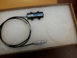
It is an optical device. It uses a DC signal for tuning purpose, however, since we don't have the manual/datasheet, we don't know the device ratings. There is a 'Lemo FFA.0S.250.CTAC' connector attached to the device to input the DC.

The device can be tuned in only 2 ways electrically which correspond to either a very high resistance or a very low one.

My aim is to measure the resistance to determine which is it. I am uploading pictures of the device so you can have a look too and if possible may be suggest me a way.

20150622_164523.jpg0618151654-01.jpg
 
Last edited by a moderator:

Status
Not open for further replies.

Part and Inventory Search

Welcome to EDABoard.com

Sponsor

Back
Top