Continue to Site

Welcome to EDAboard.com

Welcome to our site! EDAboard.com is an international Electronics Discussion Forum focused on EDA software, circuits, schematics, books, theory, papers, asic, pld, 8051, DSP, Network, RF, Analog Design, PCB, Service Manuals... and a whole lot more! To participate you need to register. Registration is free. Click here to register now.

Full Bridge SMPS's with same NP/NS give different V(out)

Status
Not open for further replies.
T

treez

Guest
Hello,
The following two LTspice simulations are almost exactly the same (both full bridge SMPS’s)…They have the same NP/NS value, but slightly different primary and secondary inductance values.

Everything else is the same about these SMPS's.

So why does the one with lower primary inductance have a higher output voltage? (316V versus 301V)

Obviously its due to the extra magnetising inductance which keeps current flow into the secondary after the FETs have turned OFF, but why isn’t this documented anywhere?

By the way, the actual turns ratio, NS/NP = 1.288, and the “official” Vout value is Vout = NS/NP*D*VIN = 294V.
 

Attachments

  • FULL BRIDGE SMPS.pdf
    15.1 KB · Views: 64
  • HVDC BRIDGE _VOUT=301V.TXT
    8.3 KB · Views: 61
  • HVDC BRIDGE _VOUT=316V.TXT
    8.3 KB · Views: 41

So why does the one with lower primary inductance have a higher output voltage? (316V versus 301V)

After power is applied, current rises more rapidly in the smaller Henry value.

Therefore you can expect greater output in the secondary, as a general rule.
 
  • Like
Reactions: treez

    T

    Points: 2
    Helpful Answer Positive Rating
Thanks, but the turns ratio is the same in each of the two full bridge's, and by the law VOUT = N.D.VIN, the actual primary and secondary inductance values shouldn't make any difference.
 

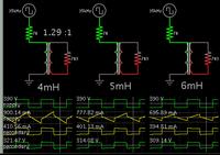
I copied values from your schematic, and created a basic raw simulation. Three transformers with slightly different primary values.

I put a tiny resistance in the primary side. As you state, the secondary produces identical voltage in these conditions.

However suppose we introduce resistance in the primary loop. (This might happen if the mosfets only partially turn on.)

Here your observation appears to be duplicated in my simulation. The secondary delivers several volts more when the primary Henry value is less.


This does not necessarily mean the higher resistance cause more energy to be transferred. That runs counter to common sense.

I don't suppose this matches your circuit exactly. It's an experiment to target the cause of the discrepancy you observed.
 
  • Like
Reactions: treez

    T

    Points: 2
    Helpful Answer Positive Rating
There are at least two reasons why the transformer inductance matters, and I believe you know it.

- D*Vin presumes that the inverter output would be zero during high-impedance phase, but that's not the case. Instead the stored inductor energy is driving the output in this phase

- the ratio of input to output voltage is not exactly np/ns. You have built in leakage iinductance.
 
  • Like
Reactions: treez

    T

    Points: 2
    Helpful Answer Positive Rating
Instead the stored inductor energy is driving the output in this phase
Thanks, and indeed it is both the magnetising current, and the current from the leakage inductance, which is driving the output during the high impedance phase, I believe.
 

Yes at lighter loads the Lmag & Imag, could go to the o/p giving higher o/p volts, at heavier loadings Lleak will dominate determining o/p volts....
 
  • Like
Reactions: treez

    T

    Points: 2
    Helpful Answer Positive Rating
It just shows that the ideal full bridge conversion expression of Vout = N.D.Vin is only for deal case of infinite primary magnetising inductance.
 

Status
Not open for further replies.

Similar threads

Part and Inventory Search

Welcome to EDABoard.com

Sponsor

Back
Top