Continue to Site

Welcome to EDAboard.com

Welcome to our site! EDAboard.com is an international Electronics Discussion Forum focused on EDA software, circuits, schematics, books, theory, papers, asic, pld, 8051, DSP, Network, RF, Analog Design, PCB, Service Manuals... and a whole lot more! To participate you need to register. Registration is free. Click here to register now.

Experimenting single phase induction motor from basic

Status
Not open for further replies.

samEEEf

Full Member level 2
Joined
Apr 17, 2010
Messages
133
Helped
1
Reputation
2
Reaction score
1
Trophy points
1,298
Activity points
2,196
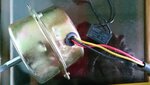
First I want to make run an single phase induction motor. I have a small single phase induction motor (used in exhaust fan) with me right now. It has three terminals - 1. Red 2. Yellow and 3. Black

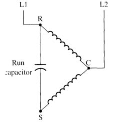
I know a capacitor is required in series with the auxiliary winding to make it self starting. I found in one document that Blue and Yellow wire are of the two terminals of main winding where black and red are from auxiliary winding. As my motor has only three terminals how I can identify the two winding? And how to connect power supply terminal and capacitor?
 

A split phase induction motor does not require a capacitor to run or start.

In those instances,, how you wire the split phase winding makes the motor to run in one direction or in reverse.

Take a picture of the motor's plate!
 

So far I know split phase motor needs a capacitor when input is single phase supply.
220v ac
Resistance is almost same. 870 ohm and 830 ohm

- - - Updated - - -

Resistance between red wire and black wire is 870 ohm
And
red to yellow is 830ohm
 

Google the term, a split phase motor does not require a capacitor.
It does have a centrifugl switch to cut out the split phase winding once a certain speed is reached.
 

A split phase induction motor does not require a capacitor to run or start.

In those instances,, how you wire the split phase winding makes the motor to run in one direction or in reverse.

Take a picture of the motor's plate!

Picture attached
 

Attachments

  • DSC_0921.JPG
    DSC_0921.JPG
    3.2 MB · Views: 95

This motor has no plate.
A plate is a small information area where it lists the motor characteristics.
I suppose that the black capacitor dangling behind the motor came with the unit.

Since both windings have the same resistance value, I would recomend that you experiment a little.

The red will be the common wire. Then connect the capacitor in series with the yellow wire. Connect the capacitor's other terminal to the black wire. Apply 220v between the red and the black wires.

If you place a small (about 1 amp) fuse when you do that experiment, the worst that it can happen is that the fuse will blow.
 

Resistance is almost same. 870 ohm and 830 ohm
That's the typical winding configuration of a "permanent-split capacitor motor" which can be run in both directions by switching the phase connection.
 

Thanks FvM to make it more clear.
As per this doc - www.rses.org/assets/serviceapplicationmanual/620-37.pdf , color of the 4 terminal of single phase motor should be blue (T1), yellow (4), black(5), Red (8). in may motor, how there are internally connected and externally only 3 wires are made available outside?
 

The schematic that FvM shows is exactly what I explained you to do. In his motor, the red wire is the common (L2).
 

The schematic that FvM shows is exactly what I explained you to do. In his motor, the red wire is the common (L2).

But told that a split phase motor does not require a capacitor.

From FvM's diagram it's clear to me. If the common connection is RED; then Terminal C is RED, terminal R is BLACK and Terminal S is YELLOW. Single phase power supply has to be given across RED and BLACK wire.

What will happen -
1. If I connect phase to RED and neutral to BLACK
2. Phase to BLACK and neutral to RED
I think, the difference is only the direction of rotation nothing else.
 

A permanent split phase capacitor motor is NOT the same as a split phase motor.

Split phase, as I explained on post #5 does not require a capacitor, but has a centrifugal switch to cut out the auxillary (split phase) winding after a certain speed has been reached.
 

A permanent split phase capacitor (PSC) motor is NOT the same as a split phase motor.
No it isn't. But the motor under discussion with three wires is more likely a PSC motor. Most small single phase operated motors (if they aren't shadow pole motors) are of this type.
 

I know.
I was explaining the subtle differences in meaning to the OP.
 

I want to know more on induction motor. Don't know whether this is the right place to do so.

I want to know about the stator winding. How many turns should it have per coil? It should be same for all motor havong same terminal voltage rating. e.g, each 230v single phase motor should have same turn per coil if we consider that the same staor material(seem iron) is used.
 

I suggest to get you an electrical machines text book and start with the basic induction motor equivalent circuit and equations.

Regarding number of turns, I would expect that most motors are setting a stator flux sufficiently but not much below core saturation to get maximum power out of a given motor size. If you know the core cross section and air gap, you can calculate it.
 

Status
Not open for further replies.

Similar threads

Part and Inventory Search

Welcome to EDABoard.com

Sponsor

Back
Top