Continue to Site

Welcome to EDAboard.com

Welcome to our site! EDAboard.com is an international Electronics Discussion Forum focused on EDA software, circuits, schematics, books, theory, papers, asic, pld, 8051, DSP, Network, RF, Analog Design, PCB, Service Manuals... and a whole lot more! To participate you need to register. Registration is free. Click here to register now.

Design of High frequency 1MHZ, 10-20 watt, PWM based inverter

Status
Not open for further replies.
dear all,
i have to make project of wireless power transmission via inductive power transfer technique..
i want to design a system of aprox 10-20watt with a gap of aprox 3cm.

i have to design a MOSFET, PWM based inverter circuit at 1Mhz frequency, a rectifier circuit and transmitting and receiving coils.

i want to simulate my results before making project.
plz help me out from where i have to start and which steps i should follow and which simulation tools will be required..

thanx
 

I believe the question has been answered in the linked previous thread. There are essiantially two parts:

- an AC magnetical field simulation of the chosen transformer gemometry, giving you a set of transformer parameters like primary and secondary inductance, coupling factor and ESR values respresenting winding resistance, skin effect and possibly core losses, if your design involves any. If your coil geometry is rotational symmetric, it can be analyzed by a simple 2.5D tool like Quickfield. If no magnetical core is involved, FastHenry can perform 3D AC magnetic simulations. If you have access to a full featured 3D EM solver, it can be used too (although it's somehow underemployed with pure AC magnetic problems).

- a circuit simulation using e.g. free LTSpice

The first step can be skipped if you already have LCR meter measurements of the coil geometry.
 

can any one help me in designing a inverter for inductive power transfer..
the specs for inverter are as follow
1MHZ
10-20Watt
PWM based
MOSFET based full bridge

can any one share circuit diagram for such inverter..
 
Last edited by a moderator:

Reference previously posted thread:

https://www.edaboard.com/threads/219997/

Hi,
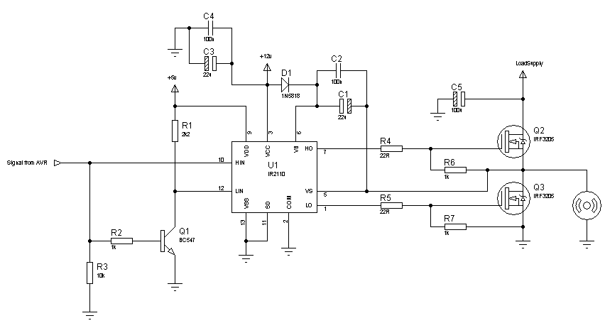
You have to use a fast switching diode at the bootstrap. So, switch to 1N5818 as the first diagram shows. Try with this circuit, I think this should work:
70_1312784222.png


Hope this helps.
Tahmid.

---------- Post added at 12:19 ---------- Previous post was at 12:17 ----------

C1, C3 - 22u
C2, C4 - 100n
C5 - 100u
R4, R5 - 22R
The rest of the resistors are in kilo-ohms.

Dear Tehmid,
can i use this inverter circuit for wireless power transmission purpose..
 
Last edited by a moderator:

use of ir2110 , MOSFET based inverter cicuit in inductive power transfer

Dear All,

i want to design a inverter circuit of 100KHZ (o/p freq) and 10-20watt to cover the air gap of 100mm aprox in my project of wireless power transmission, i need support of the forum that either the following circuit to be used in Full bridge format, can i used in wireless power transmission or i have to make some changes, please solve my problem.

https://obrazki.elektroda.pl/4181070800_1434690053_thumb.jpg

thanks in advance
 

Re: use of ir2110 , MOSFET based inverter cicuit in inductive power transfer

Most important aspect is the antenna coupling factor ( transformer coupling)

THe gap between sender and receiver must be smaller than the loop antenna for reasonable coupling. THerefore tune each coil ( round or square) to resonate more maximum Q with a large diameter > gap. ( just like RFID's in store exits) This can be extended with high mu couplers with small diameter is also self resonant to same band.

Often this causes resonant high impedance voltages that demand the use of stable film HV capacitors.

A successful method I tried was to add a turn to multi-turn RX coil and act an auto-transformer to step up current and impedance match ESR of LEDs. This boosted coupling factor of coils.

The goal is to match all impedance paths from source to load rectifier batteries. This involves high voltage E fields and high current M fields in secondary of auto- transformer.

I have seen 10 Watts transferred this way thru pavement over 100mm gap.

The easy part is find an existing SMPS that already uses a stable frequency in your region and convert the energy storage coil into an external loop or rod antenna with ferrite selected or tuned to <5% with stable resonant HV cap with high Q.
 
Re: use of ir2110 , MOSFET based inverter cicuit in inductive power transfer

Dear, Sunny
thanks for ur concern and comment...can u plz share a link of circuit diagram of the above said project of 10 watts wireless power transmission...
 

not useful for practical implementation...
any one plz do share working circuit diagram..
 

Status
Not open for further replies.

Part and Inventory Search

Welcome to EDABoard.com

Sponsor

Back
Top