AlienCircuits
Member level 5
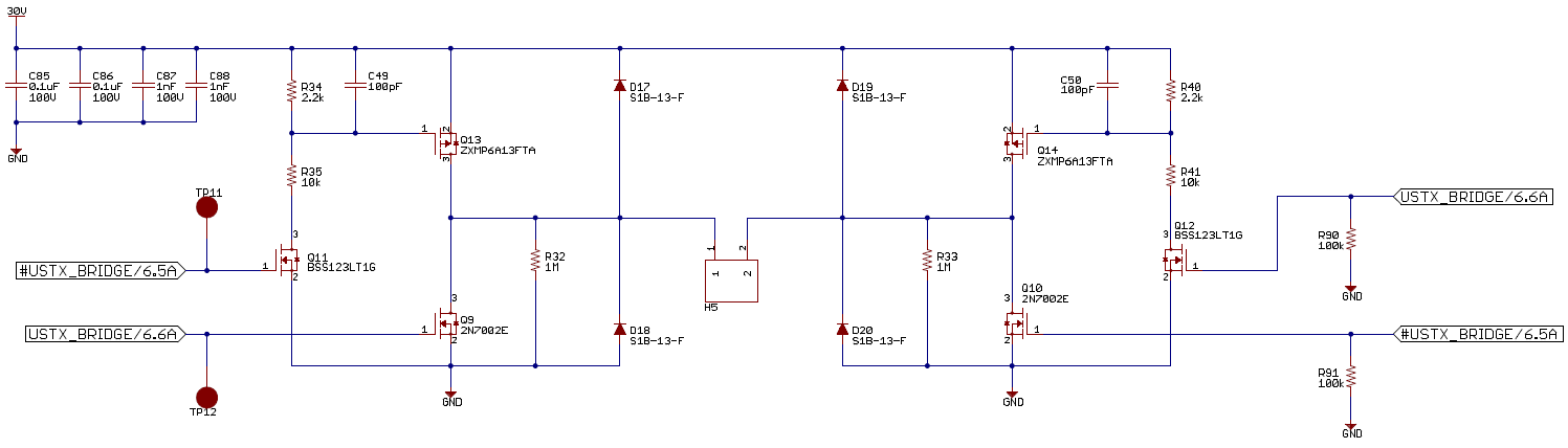
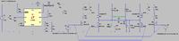
I would like to understand the flaws to my approach in the schematic.
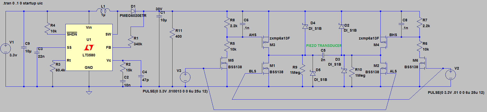
In a SPICE simulation, I simplified the ultrasonic transducer with a 2nF capacitor model.
The USTX Bridge signals will have deadtime between switches.
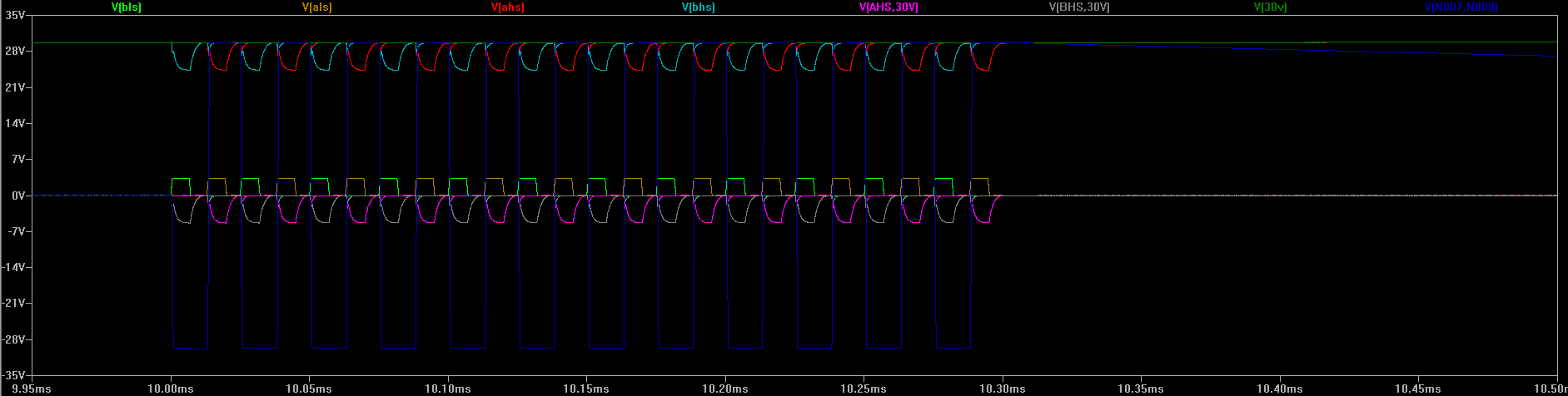
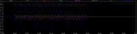
I notice losses in the simulator which is why I have come here to understand what is the problem. I see the bottom side FETs have up to 14 mA spikes through their gates as the gate capacitances are charged/discharged.
In a SPICE simulation, I simplified the ultrasonic transducer with a 2nF capacitor model.
The USTX Bridge signals will have deadtime between switches.
I notice losses in the simulator which is why I have come here to understand what is the problem. I see the bottom side FETs have up to 14 mA spikes through their gates as the gate capacitances are charged/discharged.