Continue to Site

Welcome to EDAboard.com

Welcome to our site! EDAboard.com is an international Electronics Discussion Forum focused on EDA software, circuits, schematics, books, theory, papers, asic, pld, 8051, DSP, Network, RF, Analog Design, PCB, Service Manuals... and a whole lot more! To participate you need to register. Registration is free. Click here to register now.

IGBT H-bridge 2110, microntroller does't respond on High voltage input

Status
Not open for further replies.

Shaheers

Member level 2
Joined
Mar 24, 2010
Messages
51
Helped
3
Reputation
6
Reaction score
2
Trophy points
1,288
Location
Islamabad,Pakistan
Activity points
1,616
hi,
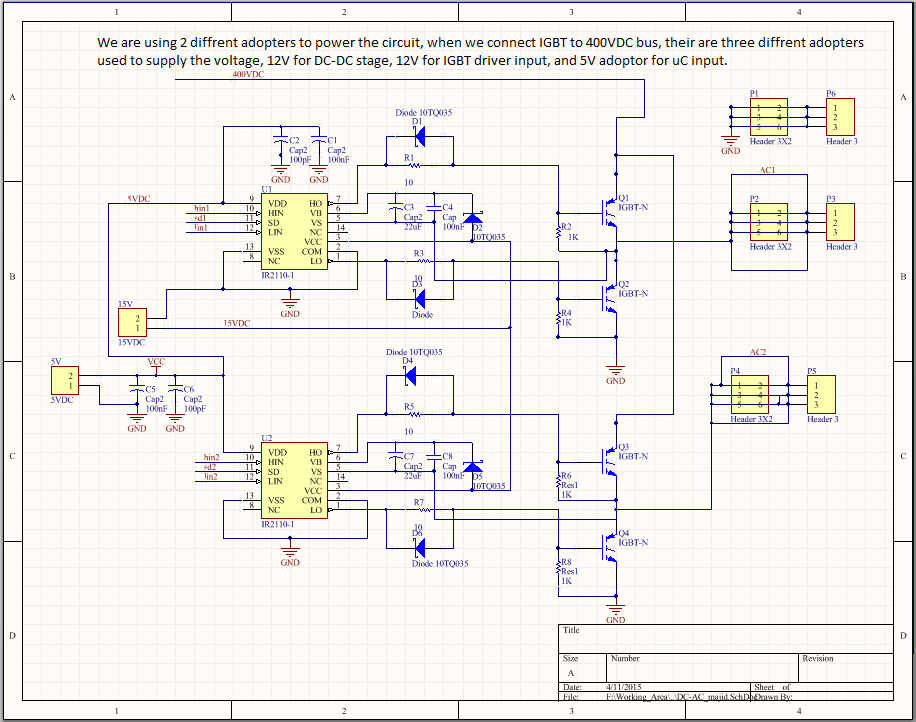
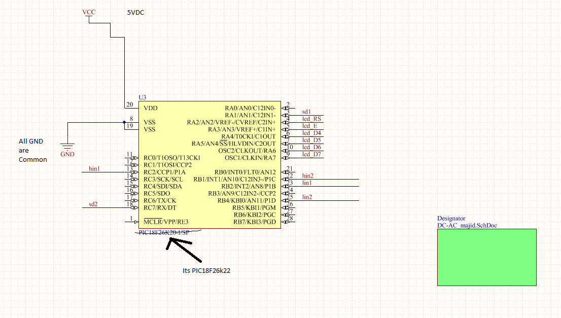
we are going to make a 2 stages sine wave inverter using IGBT H-Bridge on DC-AC stage, when we apply 12V DC power source on H-bridge the circuit works okey, but when we provides high voltage DC from DC-DC stage, which is about about 350volts at input the microntroller(PIC18f26k22) does't works. it stucks and by connecting scop at output pins it runs very slowly and gives large intervals between switch PWM pins, like timer works but controller not works,

Here is configuration we used


12VDC->sg3525+mosfet===>35VDC==>uC(PIC18F26k22 with internal osc)+ ir2110 + IGBT + RL filter ==> PSI output
 

Hi,

There are many threads on Ir2110 and inverters. Please read through them.
Here you may find good information what can be the problem.

Additionally you will find out, that it's almost impossible to give you good assistance without a valid schematic and a picture of your pcb layout.

Klaus
 

Here are the sch of all of the circuit, please tell me, DC-DC and DC-AC stages working fine independently but when we input from DC-DC stage to DC-AC stage, the microcontroller stops working,
please remember we are using IRG4pc50ud IGBTs


Hi,

first schematic:
This is not the problem you currently have: But on DC15V there needs to be a bulk capacitor (low esr, high frequency, electrolyte or tantalum) and a x7r 100n ceramics capacitor, because there is pulsed current caused by the bootstrap circuit.

third schematic:
No bulk capacitor, no high speed capacitor at VCC. MCLR is left open.

Other hints:
GND wiring between PCBs. GND plane on PCBs. EMI. signal wiring. supply voltage stable? inductors get saturated? cross conduction in IGBTs?

Klaus
 

Thanks man, can you please define what do you mean by high speed capacitors, is that mean ceramic capacitors, although we use cerimic multilayer capacitors
 

Hi,

in general: the capacitors must meet your application.

With "high speed capacitors" i meant capacitors for buffering VCC of the microcontroller. The capacitor should have reasonable low impedance at the clock frequency (and it´s overtones) of the microcontroller.
A MLCC is a good choice here. (A standard electolytic not, but it is additionally needed to compensate for load current variation and short time power fail).

Klaus
 

Status
Not open for further replies.

Similar threads

Part and Inventory Search

Welcome to EDABoard.com

Sponsor

Back
Top