Continue to Site

Welcome to EDAboard.com

Welcome to our site! EDAboard.com is an international Electronics Discussion Forum focused on EDA software, circuits, schematics, books, theory, papers, asic, pld, 8051, DSP, Network, RF, Analog Design, PCB, Service Manuals... and a whole lot more! To participate you need to register. Registration is free. Click here to register now.

[SOLVED] Problem with an old 10KV/3mA DC high voltage module

Status
Not open for further replies.
After separating two sections for diag. purpose and changing everything back to normal I have lost HV even without load. No HV at all now. I checked every connection again and they are all OK. I don't know this is good or bad but I think is better condition than before.

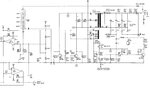
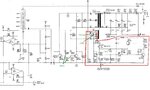
Measured supply voltage of HV transformer is about 90V (point "G"). There is no scillation at point "R" and "H". Only DC voltage. No voltage at point "P" (about few mV) which shows no feedback. At normal operation point "P" should have 10V.

I have about 1 V at point 16 which goes to CR30 and CR31 for turning them on to start oscillation. Also replaced Q12 and Q13 with new ones with about 0.6V in their bases both when I turn the unit on but still no oscillation?

Agoo
 
Last edited:

Edit better resolution schematic copy with DC and AC readings at all nodes and show if you cannot trace and debug . Not just letter TP's ,all nodes !
Must be clear.
 

Here is a higher resolution schematic. I can't play too much for measuring voltages since the unit is very old and frajile. I may make it worse. Have to be cautious.

1. Almost all components of the two oscillators are checked except C26, C27, C28 and the transformer. Is it a good idea to replace these?

2. With the 0.6 V on base of both BDY58 transistors and about 0.5V across both CR30 and CR31 do you confirm all these are off? If yes then I have to find the reason why at point "16.1" (right side of R84) voltage is low. Right?

3. Anyone has any clue why numbering in some case has a digit after decimal (instead of R48 why it is R48.1)
 

Attachments

  • hv.JPG
    hv.JPG
    145.5 KB · Views: 83
Last edited:

I have about 1 V at point 16 which goes to CR30 and CR31 for turning them on to start oscillation. Also replaced Q12 and Q13 with new ones with about 0.6V in their bases both when I turn the unit on but still no oscillation?
Agoo

U16.1 = UBEQ12.1+UCR30.1||UBEQ13.1+UCR31.1=(0.6+0.6)||(0.6+0.6) ~ 1.2V. It is right.

The absence of oscillations is the result of a low Q oscillation circuit. Check the C26 C27 C28 and and measure inductance of the transformer windings. It seems that the transformer windings are shorted.

- - - Updated - - -

3. Anyone has any clue why numbering in some case has a digit after decimal (instead of R48 why it is R48.1)
:thinker:
agoo; said:
Parts inside orange boxes (see attached schematic) are all located in a separate module
;-)
 

Comparing faulty and working HV units it seems there should be a matching pair for the oscillator to work properly. I saw a handwriting of the person from the HV company saying "BDY56 -> matched pair". I thought he means the two BDY56s should be as close together as possible but it seems one BDY56 should be matched with its pair diod. I found this when I was measuring resistivity of point "H" and "R" with respect to ground when both working and faulty units were off. I saw resistivity of point "H" on working HV unit can't be traced because it is oscillating but faulty unit shows about 23Mohm non oscillating. Swapping non oscillating BDY56 with oscillating BDY56 from the working unit I saw it start oscillating on faulty unit as well. So it seems I need to find an oscillating BDY56 as a pair for the BA157 diod at its right. Any Comment on this? Any one has similar experience of using matched pairs in electronic circuits specially oscillators? Should I find the matched pair by trial and error or is there any way for finding matched pair?
 

Points "H" and "R" should show the same resistance to ground but it would be far more useful to measure them to point 13.1 on the transformer where the winding resistance should show. The reading should be quite low, only a few Ohms at most and it should be the same from H and R.

Also try measuring the resistance between 16.1 and both 15.1 and 17.1, the readings should be identical.

Matching the two BDY56 transistors might be advantageous but I wouldn't think there would be any point in matching them to the diodes.

Brian.
 

Points "H" and "R" to point 13.1 shows 0 ohm because winding is only a few turn and copper wire is about 1 mm diameter. Same is between 16.1 to 15.1 and 17.1.
But "H" to ground resistance oscillates between infinite and about 2 Mohm. Point "R" to ground does not oscillate and is fixed about 28 Mohm. These are measurements on the working unit. Faulty unit is almost the same except the is no oscillation of ohm of "H" to ground instead resistance is fixed about 28 Mohm.

Actually these BDY56 transistors and BA157 diods are lot different. I have about 30 BDY56 and their pins resistance differ up to 10 Mohm from each other. Also the same is true with BA157 diods.
 

Measure Vdc on both sides of R84.1

If both high, 80% on 16.1 it should be biased ok ..and if it is much lower, (20%) overcurrent is in shutdown mode.
 

Points "H" and "R" to point 13.1 shows 0 ohm because winding is only a few turn and copper wire is about 1 mm diameter. Same is between 16.1 to 15.1 and 17.1.
But "H" to ground resistance oscillates between infinite and about 2 Mohm. Point "R" to ground does not oscillate and is fixed about 28 Mohm.
That doesn't make sense, if the resistance between H and R is almost zero, which is to be expected, they can't each have different resistances to ground.

What kind of test meter are you using? What you are seeing seems unusual.

Brian.
 

I checked all parts around transformer. Seems nothing is wrong or burned or faulty. The only problem I found is my BDY56 transistors are Singapore made and have very high resistivity comparing with original BDY56 transistors in the working unit (between 10-20 times higher). Specially base emitter diode of these transistors have very high forward resistances. So far I couldn't find US made or originals of these parts. I will gladly try if anyone could suggest a replacement for these diodes and transistors. Or even I will try any new design replacing for the whole part of HV output. So please welcome to post your design and suggestions.

If anyone has some of these original US or famous companies made BA157 diodes and BDY56 transistors sitting there in the drawer I will gladly accept them and will for all the costs.
 
Last edited:

The B-E resistance isn't particularly important when measured on a normal testmeter. If your meter has a range for testing diodes, try measuring with that instead. It will tell you the forward voltage drop across the junction which is probably around 0.7V and shouldn't be too far different between the two batches.

Brian.
 

Yes my tester has diode testing range. I measured B-E voltage of the three original working BDY56 I have and some of the Singapore made BDY56s. Results are as follows:

Originals:

Q13
B-E --> 486 mV
B-C --> 494 mV

Q12
B-E --> 495 mV
B-C --> 507 mV

Spare original BDY56
B-E --> 496 mV
B-C --> 504 mV

Singapor made BDY56s:

B-E (mV) B-C (MV)
1: 533 535
2: 544 545
3: 541 542
4: 546 548

About 10% higher voltages. Could this cause the problem?

As it is clear I am not good in electronics. Could someone explaine briefly how this oscillator works and what are the main elements of the oscillator here?
 

While not impossible, I wouldn't expect those differences to be significant.

The operation of the oscillator is quite straightforward. Consider first what would happen if it wasn't oscillating, R84 and R85 would provide bias current into pin 16.1 and then out through 15.1 and 17.1 to the bases of the two transistors. This would make them both conduct and current would flow from the supply into pin 13.1 and then through 12.1 and 14.1, the collectors of the transistors and to ground through their emitters. So you would have two identical circuits, both passing the same steady current and no oscillation.
However, consider what happens if the current through one of the paths varies slightly, as it will due to the inherent noise generated by the components. Now the change in current flowing through one of the transistors causes a disturbance in the magnetic field of the transformer. The change will induce a voltage into all the other windings and by virtue of the way they are wound (clockwise or anticlockwise) around the core, it changes the bias in the OTHER transistor. As this one is wired in exactly the same way, it's change on current alters the magnetic field in the other direction and opposes the change in the first transistor. The result is that within a few cycles of swinging one way and then the other, it settles into a steady oscillation by itself. Each transistor conducts for about half a cycle, turning each other on and off in sequence. The resulting changes in magnetic field in the transformer are used to generate the high voltage output, the secondary winding between 19.2 and 20.2 will have many times more turns than the primary ones and so will have a higher voltage induced into it. this is what the diodes turn into your 10KV DC output.

The control circuit can 'fine tune' the 10KV by limiting the bias current to the oscillator transistors. It does this by adjusting the current through Q14 which in turn sets the voltage at 16.1, the center tap of the transformer feedback winding.

Brian.
 

Measure Vdc on both sides of R84.1

If both high, 80% on 16.1 it should be biased ok ..and if it is much lower, (20%) overcurrent is in shutdown mode.
Did you do as I requested?

Vbe of ~0.5V is normal for a Diode tester only using 0.1mA when it is rated for 1000x more than this. We call this the threshold voltage and rated voltage depends on rated currents while mid-range bias current can be around 0.7V . This is true for all Silicon diodes and LEDs which have a different Vth and Vf. No problem there.
 

Attached is the over-current and over-voltage circuit. Any over-current or over-voltage should cause Q18 to turn off and relay K1.1 to deactivate which will cut the supply voltage of the transformer. I never saw the HV transformer supply voltage cut off, right?
 

Attachments

  • overcurrent overvoltage2.JPG
    overcurrent overvoltage2.JPG
    63.8 KB · Views: 66

Yes my tester has diode testing range. I measured B-E voltage of the three original working BDY56 I have and some of the Singapore made BDY56s. Results are as follows:

Originals:

Q13
B-E --> 486 mV
B-C --> 494 mV

Q12
B-E --> 495 mV
B-C --> 507 mV

Spare original BDY56
B-E --> 496 mV
B-C --> 504 mV

Singapor made BDY56s:

B-E (mV) B-C (MV)
1: 533 535
2: 544 545
3: 541 542
4: 546 548

About 10% higher voltages. Could this cause the problem?
Check as pair (2 4) or (2 3).
As it is clear I am not good in electronics. Could someone explaine briefly how this oscillator works and what are the main elements of the oscillator here?
royer.PNG

Here's a schematic file LTspice IV to simulate your oscillator.
View attachment Royer.zip
 

Is power off by Relay K11.1? Does K11.1 ever turn ON?

Then Momentary switch 4c toggles the fault or creates same fault emergency off,
while SPDT switch 7ac also does same, sometimes?

If No power, measure coil voltage when fault cleared at X, It should be << 2V and transistor Q18 cool, if not replace it.

- - - Updated - - -

If you want this fixed today, I suggest you markup the schematic with every voltage possible and check your connections, switch functions and supply voltage on Op Amps.
 

Relay K1.1 and Q18 and Op amps are all OK and functioning properly as I swapped half of the unit with a working one and these parts were working OK. This replacement test shows fault is in the oscillation area. It seems oscillation does not start. Feedbak voltage at point 'P' at normal operating condition should be 10V both with and without load. Now I have a few mV. When I monitor point 'P' while I turn the unit ON it start playing around to get to a stable point and finally stops at about some mV (depending on BDY56s from 50mV to 300mV). Transformer supply voltage reach limit voltage of 73 volts. Everything looks OK except oscillation dos not start. My next step is replacing the four BA157 diodes and C26,C27 and C28.
 

It looks CR30.1 and CR31.1 (BA157 diodes) are both off since voltage at point 15.1 is about -1.5 V. Base emitter voltage of Q12.1 and Q13.1 are both about 0.6 V. That is why oscillator does not start. Point "U" is 6 V. I replaced the four BA157 diodes (CR29.1, CR30.1, CR31.1 and CR32.1) and C26,C27 and C28 but no use. To me problem should be somewhere inside the red marked area attached. I even replaced Q14.1 and Q15.1 but still the same.
I don't know what this area does and what is the function of Q14.1 and Q15.1 but I think this area is causing -1.5 V at point 15.1 which cause the two BA157 diodes at the base of the two BDY56 transistors to be off. Any other idea?
 

Attachments

  • problem area.JPG
    problem area.JPG
    156.9 KB · Views: 58
Last edited:

Status
Not open for further replies.

Similar threads

Part and Inventory Search

Welcome to EDABoard.com

Sponsor

Back
Top