Continue to Site
Follow along with the video below to see how to install our site as a web app on your home screen.
Note: This feature may not be available in some browsers.
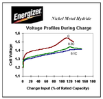
You should not use a Lithium charger circuit for a Ni-MH battery because a Lithium battery needs to have its voltage limited and the current is sensed to drop low but the Ni-MH battery does not. The Ni-MH battery needs to have its voltage sensed for a small drop that occurs when it is fully charged.
That is what is recommended by battery manufacturers like Energizer in their online Ni-MH Applications Manual and at www.batteryuniversity.com . Battery charger ICs detect the small voltage drop.How to the let voltage sensed for small drop that occurs when it is fully charged?
The datasheet from the manufacturer of your battery will show its rated mAh. Most rechargeable batteries have their rated mAh printed on them. The mAh of a battery drops when it has many charge and discharge cycles.have suggestion mah?
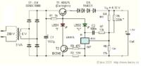
R2 is for limiting the charge current.
You can use LM317L as a sensor for 1.2V. R4 and R6 changed. The way it works; when voltage between the output of LM317L and adjust is higher than 1.2V the regulator stops current through it and LED2 goes off and so T1. 4 x 1N4001 are to give enough voltage for LED2 and LM317L. It will work down to 5V from the solar panel.