Osman Ceylan
Junior Member level 1
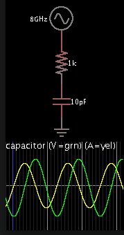
In a RC circuit, if the voltage source is a sinusoidal source, I found the given equation. C is constant.
I tried to solve this problem in time domain. So, I use a source in an EDA tool. I found the current in time. I know the voltage. I use simple numerical derivaton df(x)=[f(x2)-f(x1)]/(x2-x1). In this case, derivation is almost zero at the peak and bottom of the sinus. So, capacitance goes infinite. What am I doing wrong?

I tried to solve this problem in time domain. So, I use a source in an EDA tool. I found the current in time. I know the voltage. I use simple numerical derivaton df(x)=[f(x2)-f(x1)]/(x2-x1). In this case, derivation is almost zero at the peak and bottom of the sinus. So, capacitance goes infinite. What am I doing wrong?

")
