fravelalon
Newbie level 4
Hi, I'm developing a step down converting circuit using the Texas Instrument Converter TPS54331. I imported the PSpice model of the component and draw the circuit, but when i launch the simulation the sequent error appears: ERROR -- Convergence problem in bias point calculation
Please, can anyone help?
Thank you
This is the schematic:
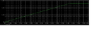
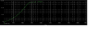
And this are the results of the simulation:
Please, can anyone help?
Thank you
This is the schematic:
And this are the results of the simulation:
**** 03/17/15 10:15:08 ***** PSpice 16.6.0 (October 2012) ***** ID# 0 ********
** Profile: "SCHEMATIC1-bias" [ C:\Users\Marco\Documents\Cubesat\5v@2,2a-pspicefiles\schematic1\bias.sim ]
**** CIRCUIT DESCRIPTION
******************************************************************************
** Creating circuit file "bias.cir"
** WARNING: THIS AUTOMATICALLY GENERATED FILE MAY BE OVERWRITTEN BY SUBSEQUENT SIMULATIONS
*Libraries:
* Profile Libraries :
.INC "C:\Users\Marco\Documents\Cubesat\5v@2,2a-pspicefiles\schematic1\bias\bias_profile.inc"
* Local Libraries :
* From [PSPICE NETLIST] section of C:\Users\Marco\AppData\Roaming\SPB_Data\cdssetup\OrCAD_PSpice/16.6.0/PSpice.ini file:
**** INCLUDING bias_profile.inc ****
.LIB ".\tps54331_trans.lib"
**** RESUMING bias.cir ****
.lib "nom.lib"
*Analysis directives:
.OP
.OPTIONS ADVCONV
.PROBE64 V(alias(*)) I(alias(*)) W(alias(*)) D(alias(*)) NOISE(alias(*))
.INC "..\SCHEMATIC1.net"
**** INCLUDING SCHEMATIC1.net ****
* source 5V@2,2A
X_U1 N14484 N14621 N15225 0 N14488 N15089 N15229 N14774 TPS54331_TRANS
C_C1 N14484 N14488 0.1n TC=0,0
D_D1 0 N14488 Dbreak
L_L1 N14488 N14499 12uH
C_C2 0 N14499 47n TC=0,0
C_C3 N14621 N14656 5600p TC=0,0
C_C4 N14621 0 120p TC=0,0
R_R1 N14656 0 12.4k TC=0,0
R_R2 N14774 N14499 10k TC=0,0
R_R3 0 N14774 1.87k TC=0,0
C_C5 0 N15089 0.015n TC=0,0
R_R4 N15225 N15229 348k TC=0,0
R_R5 0 N15225 76.8k TC=0,0
C_C6 0 N15229 10n TC=0,0
C_C7 0 N15229 10n TC=0,0
V_V1 N15229 0 12Vdc
C_C8 0 N14499 47n TC=0,0
R_R6 0 N14499 10 TC=0,0
**** RESUMING bias.cir ****
.END
**** 03/17/15 10:15:08 ***** PSpice 16.6.0 (October 2012) ***** ID# 0 ********
** Profile: "SCHEMATIC1-bias" [ C:\Users\Marco\Documents\Cubesat\5v@2,2a-pspicefiles\schematic1\bias.sim ]
**** Diode MODEL PARAMETERS
******************************************************************************
Dbreak MBR340
IS 10.000000E-15 823.900000E-09
ISR 838.600000E-09
IKF .5654
RS .1 .01827
CJO 100.000000E-15 477.200000E-12
VJ .75
M .4787
XTI 0
ERROR -- Convergence problem in bias point calculation
Last node voltages tried were:
NODE VOLTAGE NODE VOLTAGE NODE VOLTAGE NODE VOLTAGE
(N14484) 6.0000 (N14488) 33.88E-06 (N14499) 32.15E-06 (N14621) .2496
(N14656) 69.41E-06 (N14774) 5.064E-06 (N15089) .0155 (N15225) 1.1164
(N15229) 6.0000 (X_U1.OC) 131.8E-09 (X_U1.SD) 2.5000
(X_U1.2P5) 0.0000 (X_U1.CLK) 0.0000
(X_U1.ECO) 0.0000 (X_U1.ENREGS) 0.0000
(X_U1.N67875) 0.0000 (X_U1.N67893) 0.0000
(X_U1.N67911) 0.0000 (X_U1.N67943) 0.0000
(X_U1.N68245) 0.0000 (X_U1.N68385) 2.5000
(X_U1.U42_QN) 2.5000 (X_U1.U42_IN1) 0.0000
(X_U1.U45_IN2) 0.0000 (X_U1.U45_IN3) 0.0000
(X_U1.U45_IN4) 0.0000 (X_U1.U45_IN5) 0.0000
(X_U1.VREF_GM) 0.0000 (X_U1.U40_N14704) 0.0000
(X_U1.U41_N00409) 0.0000 (X_U1.U41_N02173) .8000
(X_U1.U41_N03360) -.0012 (X_U1.U41_N14122) .2500
(X_U1.U42_N00618) 6.0000 (X_U1.U42_N00718) 0.0000
(X_U1.U42_N00836) 6.0000 (X_U1.U42_N01108) 33.94E-06
(X_U1.U42_N01674) 0.0000 (X_U1.U42_N04959) 2.5000
(X_U1.U43_N00392) 0.0000 (X_U1.U43_N01530) 0.0000
(X_U1.U43_N01763) 0.0000 (X_U1.U43_N02091) 0.0000
(X_U1.U43_N02780) 0.0000 (X_U1.U45_N00466) .0325
(X_U1.U45_N00859) 0.0000 (X_U1.U45_N05307) 2.5000
(X_U1.U47_N00154) 0.0000 (X_U1.U48_N19630) 2.5000
(X_U1.X_U46.YINT) 0.0000 (X_U1.U42_N14330309) 86.64E-21
(X_U1.U42_N14330317) 2.5000 (X_U1.U42_N14330321) 0.0000
(X_U1.U42_N14330333)-215.6E-21 (X_U1.U42_N14374249) 0.0000
(X_U1.U42_N14378229) .4000 (X_U1.U42_N14379753) 0.0000
(X_U1.X_U42_U4.YINT) 0.0000 (X_U1.X_U42_U6.YINT) 0.0000
(X_U1.X_U42_U8.YINT) 0.0000 (X_U1.X_U42_U5.YINT1) 0.0000
(X_U1.X_U42_U5.YINT2) 0.0000 (X_U1.X_U42_U5.YINT3) 2.5000
(X_U1.X_U43_U3.YINT1) 0.0000 (X_U1.X_U43_U3.YINT2) 0.0000
(X_U1.X_U43_U3.YINT3) 0.0000 (X_U1.X_U42_U_DFF1.my5) 2.5000
(X_U1.X_U42_U_DFF1.qbr) 2.5000 (X_U1.X_U42_U_DFF1.qqq) -.0087
(X_U1.X_U42_U_DFF1.qint) -.2167 (X_U1.X_U45_U_INV1.YINT) 2.5000
(X_U1.X_U42_U_DFF1.qqqd1) 0.0000 (X_U1.X_U42_U_DFF1.clkdel) 2.5000
(X_U1.X_U42_U_DFF1.clkint) 0.0000 (X_U1.X_U42_U_DFF1.x2.YINT) 0.0000
(X_U1.X_U42_U_DFF1.x1.YINT1) 0.0000
(X_U1.X_U42_U_DFF1.x1.YINT2) 0.0000
(X_U1.X_U42_U_DFF1.x1.YINT3) 2.5000
(X_U1.X_U42_U_DFF1.x3.YINT1) 0.0000
(X_U1.X_U42_U_DFF1.x3.YINT2) 0.0000
(X_U1.X_U42_U_DFF1.x3.YINT3) 0.0000
These voltages failed to converge:
V(N14488) = 32.15uV \ 33.88uV
V(X_U1.SD) = 5.000V \ 2.500V
V(X_U1.U48_N19630) = 5.000V \ 2.500V
V(X_U1.U47_N00154) = -3.643V \ 0V
V(X_U1.N68385) = 5.000V \ 2.500V
V(X_U1.X_U45_U_INV1.YINT) = 5.000V \ 2.500V
V(X_U1.U42_N14330317) = 2.503V \ 2.500V
V(X_U1.U42_N01108) = 32.21uV \ 33.94uV
V(X_U1.X_U42_U_DFF1.qint) = -139.94mV \ -216.70mV
V(X_U1.X_U42_U_DFF1.qqq) = -5.598mV \ -8.668mV
V(X_U1.X_U42_U_DFF1.qbr) = 5.000V \ 2.500V
V(X_U1.U42_QN) = 2.503V \ 2.500V
V(X_U1.X_U42_U5.YINT3) = 5.000V \ 2.500V
V(X_U1.X_U42_U_DFF1.x1.YINT3) = 5.000V \ 2.500V
V(X_U1.X_U42_U_DFF1.clkdel) = 2.503V \ 2.500V
These supply currents failed to converge:
I(X_U1.E_U44_ABM5) = 144.26mA \ 36.06mA
I(X_U1.E_U48_ABM11) = -5.005nA \ -2.503nA
I(X_U1.E_U47_ABM1) = 3.646nA \ 0A
I(X_U1.X_U45_U_INV1.E_ABMGATE) = -2.500A \ -152.50nA
I(X_U1.X_U42_U_DFF1.eqb) = -2.497A \ -10.00nA
I(X_U1.X_U42_U5.E_ABMGATE2) = -2.497A \ -10.00nA
I(X_U1.X_U42_U_DFF1.x1.E_ABMGATE2) = -2.497A \ -10.00nA
I(L_L1) = 3.026uA \ 3.256uA
I(V_V1) = -18.18uA \ -18.41uA
I(X_U1.V_U43_V7) = 6.000pA \ 24.00pA
I(X_U1.V_U43_V8) = -85.87uA \ -42.93uA
I(X_U1.V_U43_V6) = -144.26mA \ -36.07mA
I(X_U1.V_U42_V11) = 132.98nA \ 135.58nA
I(X_U1.X_U43_F1.VF_U43_F1) = 85.87uA \ 21.47uA
I(X_U1.X_U42_H1.VH_U42_H1) = 3.231uA \ 3.296uA
I(X_U1.X_U42_F2.VF_U42_F2) = 3.231uA \ 3.296uA
These devices failed to converge:
X_U1.X_U48_D9.d1 X_U1.X_U42_U_DFF1.d_d11 X_U1.E_U47_ABM1
**** Interrupt ****
Last edited by a moderator: