Continue to Site

Welcome to EDAboard.com

Welcome to our site! EDAboard.com is an international Electronics Discussion Forum focused on EDA software, circuits, schematics, books, theory, papers, asic, pld, 8051, DSP, Network, RF, Analog Design, PCB, Service Manuals... and a whole lot more! To participate you need to register. Registration is free. Click here to register now.

why this converting analog sin wave to square wave does not work ?

Status
Not open for further replies.

shirko20

Member level 2
Joined
Sep 29, 2013
Messages
44
Helped
1
Reputation
2
Reaction score
0
Trophy points
6
Activity points
381
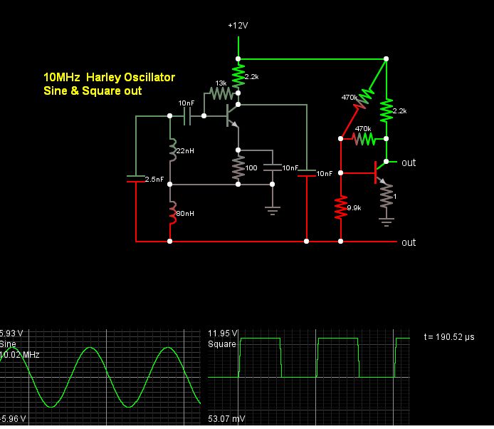
Hi masters,i have a circuit(Designed in proteus simulator) that produce a sine wave using hartley oscillator and i try to convert output wave to a square wave using LM324 IC as a comparator but it does not work here is the circuit:
Untitled.jpg
 

Show us your waveforms!

What is your frequency? The LM324 is a slooooooow device.
Depending on the frequency the output may become a trianglewave or worse.

Also-you need a little hysteresis.
 

Hello

Two things I would change, but it's up to you. Your Op-amps inputs won't like being driven higher than the supply voltage. Oscillator output of approx. 10V pk-pk @200KHz. And with one input connected to zero volts also you are most likely violating the common mode voltage range of the device as this is not a rail to rail or Over The Top device.

I would look at using a potential divider to reduce the voltages appearing on input pins to meet the requirements of the op-amp, but be careful you don't load the output of the oscillator too much. Better still use a suitable comparator and not an op-amp. If it's a job for a comparator then use a comparator is my opinion.

Thanks
Adam
 

I can only assume your oscillator that uses the bottom line on the bottom of your schematic that is cut off to left doesnt work.

This filter, like a Crystal, has very high Q parallel resonance then series notch filter just below the 3rd harmonic (if you want 200kHz , use 5.3u, 0.68u )

The feedback controlled by resonance at bandpass while the feedthru has bandpass and notch at 3rd harmonic, giving ideally >-70db THD.
 

You have the comparator - pin tied to ground but you don't have a proper negative supply. That's not good.

Get a negative supply or use a differential topology and follow arouse1973's advice to be careful about loading.
 

wooooowwwww!! here i seen to say this that i am newbie and almost could not understand 50% of your replay ,can you explain me in easier words?

- - - Updated - - -

i think the problem is with proteus simulator the oscillation work well in lack of op amp ic in the circuit board but when i add the op amp ic to screen board in proteus (just added op amp ic without any connection to any component) the wave oscillation is nothing when i delete op amp ic it get working..!!!
 

There can be startup instability problem with all the coupling capacitors.

ref your schema
C2 is going into a higher impedance, meaning slower startup, which can cause the startup bias current to oscillate at a lower frequency in a relaxation mode of oscillation inhibiting the linear mode. Reducing C2 significantly helps improve the startup. Similarily C1,C3 to a lesser extent.

Here is my cut at a sine square Harley OScillator using 2 transistors.
Except for giggles I did mine ( click here) at 10MHz for more challenge. It will take a long time to startup in slow motion sweep, so adj. simulation slider to max for a bit.

6999464900_1426206805.jpg
 
Thank you so much for your help,i love you,god bless you,
 

Hi SunnySkyguy. Nice circuit BTW. I take the point about the capacitors but it was not my design, I copied the original circuit. I thought I would carry on with the current theme of the original circuit. Looking at the circuit again the feedback capacitor will be 1.7 Ohm at 200Khz, is this really a problem? I did out of interest reduce the value but it didn't seem to improve the exponential start up time of about 800us.

Just out of interest why do you bias the shunt fed Hartley the way you have done and not use the more commonly seen PD across the supply? What's the benefit of doing it this way?

I did simulate your circuit and found the sine wave to have some transients in the output wave form. It might be a quirk with LT Spice or some thing I was doing in error. Adding an RF choke in the collector seemed to help.

Thanks
Adam
 

yes,it helped me,but can i ask you how did you measure adapted value for C1,C2 and C3?is there a formula or it is relevant to transistor biasing?

- - - Updated - - -

and what simulation application is suitable for analog circiut that have a oscilloscope instead of Proteus?Has PSpice simulator an Oscilloscope in it?
 

Problem with wave generation in Proteus?

Hi,with my regret to all member and master
I have a problem with this circuit in proteus simulator ,that is when i lack of OP_AMP ic in circuit (deleting it) every thing works good and oscilloscope show generated Hartley sine wave, but in exist of OP_AMP-IC the wave generation is just an straight line (no wave generates) even this op amp is not connected to anything?please tell me how to fix this problem?(i want to use op amp as a wave converter.)
HERE IS CIRCUIT:hartley circuit.jpg

- - - Updated - - -

correction "with my regard" not unmeanable regret
 

It's quite normal that a SPICE oscillator simulation stays in steady state with no oscillations, although the real circuit does oscillate. This happens because the initial transient solution puts the circuit in perfect balance.

It's not so clear why the circuit oscillates without an OP component placed in the circuit, I can just guess that some simulator settings are automatically changed, if so, it's one of the typical Proteus intransparencies.

The usual methods to start oscillations are
- skip initial transient solution. A standard SPICE option, don't know how this is accomplished in Proteus.
- add some kind of "kick start" to the circuit, e.g. step the power supply after simulation start, or inject a small pulse into the oscillator
 

It gives this error: error : [SPICE]Gmin step[110 of 120] failed:GMIN =5.62341e-012
what means it?
 

Some simulators don't like components on the schematic which are not connected. To see if this is the case, connect up the power pins.
Adam
 

yes that error was because of what you mention to it but still when op_amp is connected as a comparator oscilloscope shows nothing?while in lack of op_amp everythings work good!
 

I think that's because of what I mentioned. When the output goes negative the op-amps internal ESD devices kick in and effectively short out the input. You may want to try the 10K resistor I have in my design on the non inverting input. I don't have the same op-amp in my simulator so I can't try it. I must download the model and try it.
Thanks
Adam
 

i replaced op-amp with a high speed comparator ad8001 ic but steel nothing put outs!
 

You did not read my last post. Look at my circuit I did for you, it has nothing to do with speed.
Adam
 

Status
Not open for further replies.

Part and Inventory Search

Welcome to EDABoard.com

Sponsor

Back
Top