Continue to Site

Welcome to EDAboard.com

Welcome to our site! EDAboard.com is an international Electronics Discussion Forum focused on EDA software, circuits, schematics, books, theory, papers, asic, pld, 8051, DSP, Network, RF, Analog Design, PCB, Service Manuals... and a whole lot more! To participate you need to register. Registration is free. Click here to register now.

why this converting analog sin wave to square wave does not work ?

Status
Not open for further replies.
i tried 10k resistor but no succeed
 

Re: can any one complete this circut to convert generated output sine wave to square

You can not expect a Square Wave directly off of the tank circuit.
You must First run the signal into a buffer amplifier and then into a limiting (clipping) amplifier circuit and then you will get something that may resemble a square wave.

FWIW

jer :)
 
Last edited by a moderator:

Hello

Looking at the spec of this op-amp, you really need to look at using a comparator or the circuit Sunnyguy drew for you. Even when you have the input pins within the limits of the device you still have to consider input signal level, slew rate and GBP etc. The device you have chosen is a general purpose device, so no bells and whistles I am afraid.

For the output to switch fast enough to resemble a square wave you need quite a bit of gain but at 200KHz your gain is going to be small for this op-amp it not likely to work properly unless you reduce the frequency.

You may see something at around 20KHz but it's more likely to look like a triangle wave. Drop down the frequency to 2KHz and it will look square ish but not very good. That's why you should use a comparator circuit.

Thanks
Adam
 

LOL, yeah after reading the data sheet I found out just how general purpose they are :)
Adam
 

I used Proteus and introduced a single kick start pulse and the osc starts to oscillate. pic 1 & 2.

Then I replace LM324 with LM393 comparactor and I was able to get a nice square wave. pic 3.

Allen
 

Attachments

  • SIN2SQR_1.PNG
    SIN2SQR_1.PNG
    162 KB · Views: 88
  • SIN2SQR_2.PNG
    SIN2SQR_2.PNG
    21.1 KB · Views: 78
  • SIN2SQR_3.PNG
    SIN2SQR_3.PNG
    93.6 KB · Views: 78
Last edited:

U1A must have +/- inputs at the same DC voltage near V+/2

Fix that and you will get 50% pulse

Signal is AC coupled to gnd at present while (+) is based to V+/2 !!
 
Your're right. After adding C5 and C8, the square wave looks much better.

Allen
 

Attachments

  • SIN2SQR_4.PNG
    SIN2SQR_4.PNG
    41.2 KB · Views: 80
  • SIN2SQR_5.PNG
    SIN2SQR_5.PNG
    93.3 KB · Views: 80

thank you guys you all helped me to understand
 

we can use one diode as sine wave to square converter but it is not recommended in more frequencies !why it is not recommended?
 

we can use one diode as sine wave to square converter but it is not recommended in more frequencies !why it is not recommended?
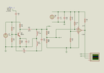
A diode or a few diodes will not convert a sinewave into a squarewave. A diode simply conducts current when it is forward biased and blocks current when reverse biased. Some diodes are fast and can rectify many frequencies but other diodes are slow and can rectify only low frequencies.
 

but how diodes
convert ac sine wave power to dc power?
 

You need to learn about basic electricity to see half-wave and full-wave rectifiers, how they rectify the AC sinewave into positive or negative rounded pulses and see how a filter capacitor can smooth the pulses into DC.
There are many links to rectifiers in Google but here is one good link: https://en.wikipedia.org/wiki/Rectifier
 

Status
Not open for further replies.

Part and Inventory Search

Welcome to EDABoard.com

Sponsor

Back
Top