Welcome to our site! EDAboard.com is an international Electronics Discussion Forum focused on EDA software, circuits, schematics, books, theory, papers, asic, pld, 8051, DSP, Network, RF, Analog Design, PCB, Service Manuals... and a whole lot more! To participate you need to register. Registration is free. Click here to register now.
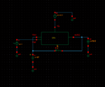
* I don`t see an opamp - it is an OTA, correct?
* More than that, it seems that you are applying POSITIVE feedback; WHY?
* The test signal must be feeded into the loop directly!
* I don`t see an opamp - it is an OTA, correct?
* More than that, it seems that you are applying POSITIVE feedback; WHY?
* The test signal must be feeded into the loop directly!
I am not sure what you want to simulate:
a) Open-loop gain - that is the gain of the active device without any feedback
b) Loop gain - that is the gain od the complete feedback loop (amplifier and feedback path in series)
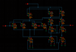
Having a large inductor in the negative feedback (as you show in your screenshot) is a common way to simulate open-loop gain. The large value inductor in negative feedback ensures correct DC biasing. For AC analysis it is out of the picture. You should make sure that the feedback is connected in a negative feedback scheme.
I mean that when you run an AC simulation (i.e. to look at the open loop gain) with a very high value inductor in the feedback, the inductor impedance will be very high at those AC frequencies, so at AC frequencies it will look like you have an open-loop. At DC, the inductor has 0 impedance, so it appears like a short, so for DC solution you will have a feedback ensuring the correct DC voltages.
Having a very large resistor in feedback is also an option, but it will probably affect your AC simulation results.
This site uses cookies to help personalise content, tailor your experience and to keep you logged in if you register.
By continuing to use this site, you are consenting to our use of cookies.