Continue to Site

Welcome to EDAboard.com

Welcome to our site! EDAboard.com is an international Electronics Discussion Forum focused on EDA software, circuits, schematics, books, theory, papers, asic, pld, 8051, DSP, Network, RF, Analog Design, PCB, Service Manuals... and a whole lot more! To participate you need to register. Registration is free. Click here to register now.

Push Pull Converter with Load - voltage drop Issue

Status
Not open for further replies.

emaniac

Member level 1
Joined
Feb 24, 2014
Messages
35
Helped
0
Reputation
0
Reaction score
0
Trophy points
6
Activity points
303
Hi,

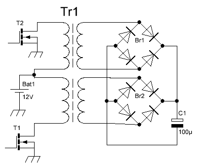
Designing a push pull converter using SG3525. I have 400watt, 350V secondary transformer( I didn't design one, but purchased). When I connect Load there is a huge drop in voltage.

push-pull-skel.jpg

When I check the Voltage at the output of the connection above, I have 350V. When i add a capacitor (180uF, 450V) the voltage drops to 295V.
Diodes used - MUR460

Now if I add a Load (15 Watt ), Voltage drops to 160V at the output. As mentioned in other Post I checked if Battery Voltage is dropping, But No, Battery Volt is 12.

Current from Battery is 0.9A @12V
Current to Load is 0.05A @ 160V
And Yeah, PWM duty is 50%

I don't Know which part of the design needs attention.
Regards,
 

Connect the output of the device through a step down transformer to the inverting input of the SG3524 and connect the non inverting pin to a reference voltage.
This ensures that the output is constant at all times, if you are confused please read the datasheet of SG3524.
 

Hi Ogu Reginald,

Thank you,
I have a feedback to the Inverting Input of the PWM Controller. As I mentioned above, the Duty Cycle is already 50% and the Voltage is just 160V (with feedback).
A simple potential divider 63K and 1K (for 330V out) With Load the Feedback Voltage is 2.5V.

Regards
 

Feedback from the output will cause the PWM to change which will boost the dropping output voltage back to almost normal when the output is loaded.
 

Hi Audioguru,

I checked the duty cycle of the Gate signals with a scope. It is 50% under load and No load (No change to duty cycle) with a Potential divider feedback. I already have the maximum duty cycle, but not the expected output voltage.

I don't see a particular reason why this is happening.
 

The SG3525 IC is very old, I found the datasheet for the newer improved SG3525A but it doesn't say what is improved.
I do not know why it limits the duty-cycle to 50%. Then your unloaded or average duty-cycle must be reduced so that when the circuit is loaded the duty cycle can increase.
 

Thank you for the replies
ALERTLINKS,
Frequency is 50kHz, It isn't too high right?
Audioguru,
Do you mean in a push pull converter duty can be more than 50%
I always thought for ''push and pull'' we need 50% or less. Please explain me a bit.

How do I fix this now? I don't understand why adding a capacitor is giving such a huge drop. I don't really know where the volt is going :'(
 

See if the two output loops are properly phased. This transformer is not made center=taped normally but there is a single loop which connects to bridge rectifier. Sometimes there is separate bridge on each loop.
 

If the output is at 50% then the loop is not closed and
no regulation can occur. You are operating based on a
fixed core magnetization and trading voltage for current
against that fixed energy "slug". Probably you are not
using a high enough turns ratio or core size (?) - at full
load your 50% inputs need to produce at least the
desired voltage.
 

Is your transformer designed to be oriented the way you are using it, or was it designed to be oriented in the reverse direction? In other words, are using the primary as the secondary, and vice-versa?

What is the DC resistance of your secondary? As measured with an ohmmeter? It will privide a clue to how much load you can put on it.

Try changing the switching frequency, to see if output increases.
 

Hi all,
Thanks for all your suggestion.

I thought I will start fixing it step by step.
Gate Signals are as expected.

I expected the Input to transformer(Centre of Trans and Drain of MOSFET1) be ON(12V for 10us) and OFF(0V for 10us) for 50kHz

But What I observed on the scope is 6V positive for 10us and 6V negative for 10us.
The same I could Observe at the secondary. 165V positive and 165V negative. And obviously the output of the diode is 165V.

Regards
 

Firstly, the MUR460's are too low in volts, they see 650V (+ spikes) for 325V out, put two in series in place of the singles..! one of these may have died...

Check the zero volt returns on the circuit, looks like you are losing a few volts some-where,, if you look D-S on the fets you should see 0 and +24V, with a small turn off volt overshoot. If you don''t see this maybe only one fet is working...

Was this product intended to provide 325V out or only 165V (for a 110Vac inverter)?
 
Last edited:
Hi Orson Cart,
Greetings!

looks like you are losing a few volts some-where
The output of the Transformer is +165V and -165V because the input of the Transformer is +6V and -6V
Using a diode as mentioned in post #1 is giving an output of 165V

put two in series in place of the singles..! one of these may have died...

Thank you, I will definitely add two diodes in series.

Was this product intended to provide 325V out or only 165V (for a 110Vac inverter)?

This Transformer is designed for 350V output(Considering max duty obtainable from SG3525) for 220Vac inverter. So with SG3525 I could Adjust the duty accordingly and so the DC bus.


Hi ALERTLINKS,
Sometimes there is separate bridge on each loop.
I tried adding a separate bridge on loop1 and the output volt was 460. Strange!
Can you please explain me what exactly you meant by adding a separate bridge on each loops.
 

You can check the phase by shortening the loops end together (diode points). If heavy current flows in primary then it is OK or connect this way.
5267618400_1426255371.png
 

How do I fix this now? I don't understand why adding a capacitor is giving such a huge drop. I don't really know where the volt is going :'(

There is a lot of good advice from the posters above. To know exactly which is the root cause and the solution to your problem, we (and by "we" I'm including you) must see scope waveforms around several points within the circuit.
Do you have a scope? If not can you borrow one?
 

Hi,
Sorry for the delay and thanks for all the valuable replies.

ALERTLINKS,
I tried what you mentioned, Rectifier for each loop. The output for 15watts load is 330V, 40 Watts is 300V and 100Watts is 260V. The transformer is supposed to be 350V out.

Using UF4007 as rectifier, believe I've not broken its limits yet.

schmitt trigger,
I have a scope and I can check the waveforms.
 

It's ferrite transformer, at 50kHz
 

It looks at tho the VA rating of the Tx is not high enough, measure the resistance of the windings (pri & sec), multiply this by the currents you see/want and see if this correlates to the volt drops you are seeing....
 
Status
Not open for further replies.

Similar threads

Part and Inventory Search

Welcome to EDABoard.com

Sponsor

Back
Top