Continue to Site

Welcome to EDAboard.com

Welcome to our site! EDAboard.com is an international Electronics Discussion Forum focused on EDA software, circuits, schematics, books, theory, papers, asic, pld, 8051, DSP, Network, RF, Analog Design, PCB, Service Manuals... and a whole lot more! To participate you need to register. Registration is free. Click here to register now.

feedback using optoisolator and tl431

Status
Not open for further replies.

--BawA--

Advanced Member level 1
Joined
Nov 28, 2012
Messages
479
Helped
43
Reputation
86
Reaction score
42
Trophy points
1,318
Location
Noida, INDIA
Activity points
4,926
Hi everyone,
i am trying to eshtablish an isolated feedback loop for my forward converter, currently i am referring to "POWER SUPPLY COOKBOOK BY MARTY BROWN"
opto.png
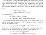
i am also attaching an image ,in which the dimensioning of the resistors are carried out,
opto1.png
the controller ic is UC3843
, now can someone explain me why why Icc max is 1.2ma?
and how did they calculate the value of R1?
 

TL431 is working as a comparator (with internal 2.5V reference). More details on page 21 of its datasheet:

https://www.ti.com/lit/ds/symlink/tl431.pdf

tl431-comp.gif

R1 (from your schematic) should allow a minimum biasing current of 1mA through TL431 cathode (input) for a normal operation.
 

But , in that book it has written that the error amp of uc3843 is disabled and error ampifier is setup on secondary side using tl431.
In the calculation of r1 why the numerator is 0.5?
 

TL431 is working as a comparator (with internal 2.5V reference).
A potentially misleading statement. TL431 can be used as a comparator, but working as compensated feedback amplifier in most SMPS applications, e.g. the circuit shown in post #1.
 
There was an error (typo) on your book; they're not actually talking about R1 but R2 (the series resistor from the detector side).

They are talking about Ifb current (the current flowing through optocoupler detector) and the 4.5V voltage level at the compensation pin. Thus the voltage across R2 should be the difference between Vref (5V) and Vcomp (4.5V).

- - - Updated - - -

A potentially misleading statement. TL431 can be used as a comparator, but working as compensated feedback amplifier in most SMPS applications, e.g. the circuit shown in post #1.

It's still an open loop circuit for DC (low frequency) operation as there's no direct (resistive) feedback path from output to input. Anyway, seems like the open loop gain is quite low so there's no need for pure resistive negative feedback.
 
Last edited:

It's still an open loop circuit for DC (low frequency) operation as there's no direct (resistive) feedback path from output to input. Anyway, seems like the open loop gain is quite low so there's no need for pure resistive negative feedback.

Many power supply feedback amplifiers are "open loop for DC", in other words have integral behaviour. The most simple case is a PI controller, which has "infinite" respectively very large gain at DC. As a well known property its steady state error approaches zero. The same behaviour is usually intended for power supplies.
 

    V

    Points: 2
    Helpful Answer Positive Rating
In the calculation of Ifb max it's (4.5 - 0.3)/820. (in the attached image)
why not it's (5 - 0.3)/820 ?
 

It's an Ifb current swing rather than absolute current calculation.
 

FvM said:
It's an Ifb current swing rather than absolute current calculation.
please explain a bit more,,
One terminal of resistor R2 is connected to fix Vref which is 5V , and the other terminal(compensation pin) can vary from 4.5V to 0.3V , so IFb max will occur when , the one other terminal is at 0.3V , so the calculations should go like (5V-0.3V)/R2
isn't it ?
 

Ifb is swinging between Ifb,min and Ifb,max. Ifb,min, which is the converted TL431 quiescent current has been calculated before. Now the increment is calulated. As Ifb,min refers to 4.5V feedback voltage, the voltage swing is 4.5 - 0.3V and the current swing is 4.2V/820 ohm.

I'm just retelling what's written in the text. It seems to me that the calculation isn't completely correct because it doesn't account for optocoupler transfer ratio variations. Please don't held me responsible for the text book's weaknesses and potential faults. In case of doubt start your own calculation from the scratch.
 

Can any one help me to design the complete feedback network with the help of TL431 and PC817 , Kindly explain with some example , and how the values of resistor are calculated?
I have a book , but it contains some error,
also i tried alot on searching it on internet but couldn't find the detailed explanation.
I am designing a forward converter with UC3842 , of following rating
Input voltage 90VAC to 270VAC
Output voltage 14.2 VDC
Power 200 Watt
 

Status
Not open for further replies.

Part and Inventory Search

Welcome to EDABoard.com

Sponsor

Back
Top