Continue to Site

Welcome to EDAboard.com

Welcome to our site! EDAboard.com is an international Electronics Discussion Forum focused on EDA software, circuits, schematics, books, theory, papers, asic, pld, 8051, DSP, Network, RF, Analog Design, PCB, Service Manuals... and a whole lot more! To participate you need to register. Registration is free. Click here to register now.

Why this is not working ?

Status
Not open for further replies.
Start timer1 on zero crossing. After the whole period, read its value. From it determine required delay for each step by dividing with number of steps.
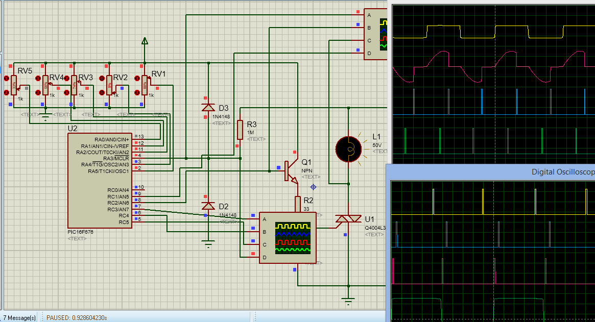
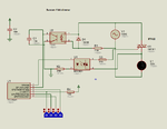
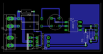
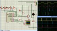
I just coded 5-ch dimmer using PIC16F676. I don't know were it can be used.
 
I am designing a touchscreen and voice controlled switch board. I will be using chipKit MAX32 board to drive a 7 inch TFT + Touchscreen. There will be no physical buttons. All buttons are touchscreen based. For voice control I am using mikroE Speakup. I need to control 8 SSRs and 2 triac. Can I use non ZC, optically isolated, triac based SSR (Solid State Relay) for dimmer ? In Proteus there is no PIC32 hence I am testing using PIC and Proteus. If it works fine then I will test in hardware and later I will rewrite the code for PIC32 using mikroC PRO PIC32 Compiler. I also have to design GUI for TFT using Visual TFT. The voice feature is for visually impaired and it is optional. The feature will be implemented but if SpeakUp is omitted then it will be touchscreen based switch board. If there are blind person then they can include it. The dimmer is used for fans.

I think PIC32 has 32 bit timers and it can handle triac firing better.


The switch board will be like this. Some will have pluf points and some without. The main menu contains buttons like Kitchen, Bed room1, Bedroom2, Living room, etc... Lets say if you are in bedroom and want to turn off kitchen light, you will have two ways. touch the kitchen button on bedroom switch board and kitchen control panel appears and you can see the status of kitchen lights and appliances. You can then control them. Also you can control kitchen devices from any other room using voice. Each SpeakUp can have 200 voice commands. So, for turning ON/OFF it can control 100 devices. There will be XBee in each switchboard for communication between switchboards. I need more than one UART, one for SpeakUp, one for XBee, etc... and I want TFT screen to be fast changing between screens and hence PIC32.
 
Last edited:

Edit:

Sunrom 256 step dimmer code attached.

- - - Updated - - -

Here is new code for sunrom 256 step dimmer. The previous code was doing a lot of mathematics due to the instruction


Code C - [expand]
1
dimmerVal = PORTA * (-1) + 255;


I replaced it with simple assembly code.


Code C - [expand]
1
2
3
4
5
6
7
8
9
10
11
12
13
14
15
16
17
18
19
20
21
22
23
24
25
26
27
28
29
30
31
32
33
34
35
36
37
38
39
40
41
42
43
44
45
46
47
48
49
50
51
52
53
54
55
56
57
58
59
60
61
62
63
64
65
66
67
68
69
70
71
72
73
74
75
76
77
78
79
80
81
82
83
84
85
86
87
88
89
90
91
92
93
94
95
96
97
98
99
100
101
102
103
104
105
106
107
108
109
110
111
112
113
114
115
unsigned int zc = 0, i = 0;
unsigned int dimmerVal = 0, dummy;
 
sbit Gate_Trigger at LATB7_bit;
sbit Gate_Trigger_Direction at TRISB7_bit;
 
struct {
   int B0:1;
   int B1:1;
   int B2:1;
   int B3:1;
   int B4:1;
   int B5:1;
   int B6:1;
   int B7:1;
   int B8:1;
   int B9:1;
   int B10:1;
   int B11:1;
   int B12:1;
   int B13:1;
   int B14:1;
   int B15:1;
} myVar;
 
 
//Timer interrupt is every 32 us
 
void interrupt() {
 
    if(RCIF_bit) {
        //dimmerVal = UART1_Read() * (-1) + 255;
        RCIF_bit = 0;
    }
 
    if(INTF_bit) {                                //INTx interrupt is every 10 ms
        INTF_bit = 0;                             //This block executes within 10 us
        INTE_bit = 0;
        Gate_Trigger = 0;
        i = 0;
        if(dimmerVal == 0) {
             Gate_Trigger = 1;
             Delay_us(50);
             Gate_Trigger = 0;
             INTE_bit = 1;
             T0IE_bit = 0;
        }
        else {T0IE_bit = 1; TMR0 = 96;}
        
        zc = 1;
 
        INTEDG_bit = ~INTEDG_bit;
 
    }
     
    if(TMR0IF_bit) {                                      //This block executes within 10 us
        TMR0IF_bit = 0;
        TMR0 = 96;
        if((zc) && (i == dimmerVal)) {
             T0IE_bit = 0;
             INTE_bit = 1;
             Gate_Trigger = 1;
             Delay_us(50);
             Gate_Trigger = 0;
             zc = 0;
        }
        ++i;
     }
}
 
void main() {
 
     OPTION_REG = 0x88;
     
     ANSELA = 0x00;
     ANSELB = 0x00;
     ANSELC = 0x00;
     ADCON1 = 0x90;
 
     IOCBP = 0x00;
     IOCBN = 0x00;
     
     TRISA = 0xFF;
     TRISB = 0x01;
     TRISC = 0x80;
     
     PORTA = 0x00;
     PORTB = 0x00;
     PORTC = 0x00;
     
     LATA = 0x00;
     LATB = 0x00;
     LATC = 0x00;
     
     UART1_Init(9615);
     Delay_ms(200);
     
     RCIE_bit = 1;
     INTEDG_bit = 0;
     INTF_bit = 0;
     INTE_bit = 1;
     PEIE_bit = 1;
     GIE_bit = 1;
 
     while (1) {
     
          dummy = PORTA;
          //dimmerVal = PORTA * (-1) + 255;
          
          //asm clrw
          //asm movf _dummy+0, W
          asm xorlw 0xFF
          asm movwf _dimmerVal+0
     }
}


- - - Updated - - -

Improved version. Added a button for toggling dimmer value.

- - - Updated - - -

Added button to select PORTA or UART for dimmer data.

- - - Updated - - -

Edit 2:

This is the actual circuit of Sunrom 4 bit dimmer. I have traced it 10 times and I have used continuity checking to check what components and what pins of PIC connect. I have few questions to ask.

1. There is no 10k pullup on collector of PC817. So, have they enabled weak pullup on GP1 pin ?

2. They are not using INT pin for ZC buy using GP1 pin. Does that mean they are using IOC to detect ZC ?

3. what are the values of resistors. I have mentioned what is printed on the SMD resistors.

4. What does R4 do ?
 

Attachments

  • sunrom 256 step dimmer ver2.png
    sunrom 256 step dimmer ver2.png
    131.3 KB · Views: 109
  • sunrom 256 bit dimmer rev4.rar
    164.4 KB · Views: 101
  • sunrom 256 bit dimmer rev5.rar
    168.4 KB · Views: 103
  • sunrom 256 step dimmer ver2 button.png
    sunrom 256 step dimmer ver2 button.png
    134 KB · Views: 115
  • sunrom 256 bit dimmer rev6.rar
    43.7 KB · Views: 96
  • dimmer ver6.png
    dimmer ver6.png
    137.8 KB · Views: 99
  • sunrom 4 bit.png
    sunrom 4 bit.png
    29.5 KB · Views: 118
Last edited:

PC817 can't work without pullup. You can check 5V pulse on the input pin. IOC equally works well, infact with smaller code. I have used it in 5ch version. Even polling the pin for a certain time can do and it can also limit the frequency range. Value of R2 and R3 is 470-ohm, R4 is 10K, I guess. Again you can check it with multimeter. If there is no input connected, It will make logic hi at that pin. I think the other three inputs are internally pulled up so there will be no output. You can check this dimming output without connecting input switches.

From datasheet,
Every GPIO pin on the PIC12F629/675 except GP3, has a weak pull-up option. .
 
That's what I asked will PC817 work with GP1's internal weak pullup ?
 

I have made new layout for sunrom 4 bit dimmer. Is it ok ? How to place SMD components on bottom layer in eagle ?

- - - Updated - - -

In sunrom modules they have placed PTH components on top layer and SMD components on botton layers and they have avoided vias. Please tell me how to place SMD components on bottom layer in eagle. In my design there are a lot of vias. I want to avoid it.

- - - Updated - - -

I reduced from 17 vias to 6 vias. Here is final layout of sunrom 4 bit dimmer. I will soon port the eagle file. I came to know how to place SMD components on bottom layer from here.

https://www.instructables.com/community/eagle---how-to-put-smt-components-on-bottom-layer/
 

Attachments

  • sunrom 4 bit dimmer new layout.png
    sunrom 4 bit dimmer new layout.png
    44.9 KB · Views: 110
  • sunrom 4 bit dimmer lyt.png
    sunrom 4 bit dimmer lyt.png
    73.4 KB · Views: 90

I made eagle layout for this circuit.

https://arduinodiy.wordpress.com/2012/10/19/dimmer-arduino/

Will post eagle files soon. The small layout shows the actual size of the board.

- - - Updated - - -

New and final layout.

- - - Updated - - -

Related to post #83


Code C - [expand]
1
dimmerVal = dimmerVal * (-1) + 255;


can be replaced by


Code C - [expand]
1
dimmerVal = dimmerVal ^ 0xFF;


or


Code C - [expand]
1
dimmerVal ^= 0xFF;


Attachments

  • dimmer lyt.png
    dimmer lyt.png
    61.8 KB · Views: 92
  • zc lyt rev1.png
    zc lyt rev1.png
    52.3 KB · Views: 90
Last edited:

Status
Not open for further replies.

Part and Inventory Search

Welcome to EDABoard.com

Sponsor

Back
Top