Continue to Site

Welcome to EDAboard.com

Welcome to our site! EDAboard.com is an international Electronics Discussion Forum focused on EDA software, circuits, schematics, books, theory, papers, asic, pld, 8051, DSP, Network, RF, Analog Design, PCB, Service Manuals... and a whole lot more! To participate you need to register. Registration is free. Click here to register now.

Why this is not working ?

Status
Not open for further replies.
AC type opto ? There is no diode or bridge then how he get ZC pulses.
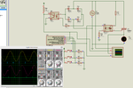
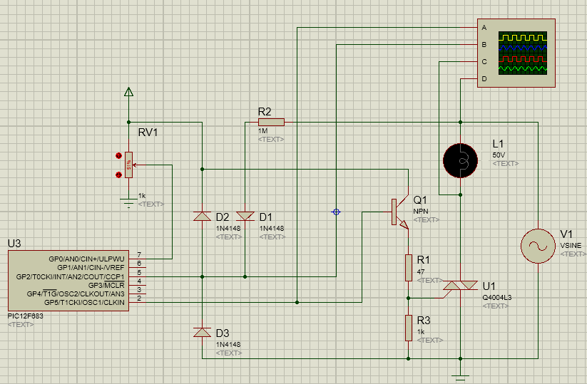
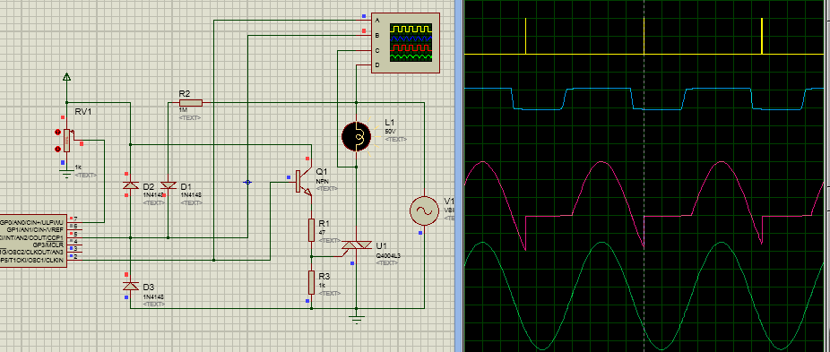
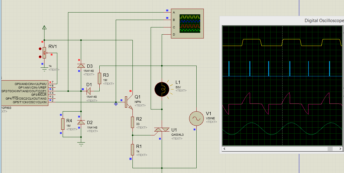
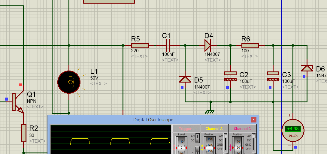
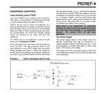
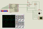
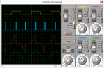
There is a parallel diode, so surely no AC opto-coupler. Simply assume that the circuit is triggering with halfwave zero-crossing signal on both edges.
 
Ok.

Three buttons dimmer. I will soon post the PCB layout files.


Edit: There is a bug. The negative half cycle is not controlling. Why ?
 

Attachments

  • Three Buttons Dimmer.rar
    157.6 KB · Views: 99
  • three buttons dimmer.png
    three buttons dimmer.png
    139.1 KB · Views: 150
Last edited:

Yes, you are right. 220V was the problem in Proteus. Works fine with 50V VSINE. Here is new code.


Edit: Eagle PCB files attached for three buttons dimmer.


Code C - [expand]
1
2
3
4
5
6
7
8
9
10
11
12
13
14
15
16
17
18
19
20
21
22
23
24
25
26
27
28
29
30
31
32
33
34
35
36
37
38
39
40
41
42
43
44
45
46
47
48
49
50
51
52
53
54
55
56
57
58
59
60
61
62
63
64
65
66
67
68
69
70
71
72
73
74
75
76
77
78
79
80
unsigned char milliSec = 0, i = 0;
 
//Timer0
//Prescaler 1:4; TMR0 Preload = 6; Actual Interrupt Time : 1 ms
 
//Place/Copy this part in declaration section
void InitTimer0() {
    OPTION_REG = 0x81;
    TMR0 = 6;
    INTCON |= 0x20;
}
 
void interrupt() {
 
     if(INTF_bit) {          //ZC occurs once every 10 ms
        INTF_bit = 0;
        i = 0;
        if(milliSec == 0) {
             GP5_bit = 1;
             Delay_us(50);    //INTF occurs once every 10 ms. So, it is safe to use 50 us delay
             GP5_bit = 0;
        }
        else InitTimer0();
     }
     
     if(T0IF_bit) {        //Timer interrupt occurs every 1 ms
        T0IF_bit = 0;
        TMR0 = 6;
        //Enter your code here
        if(i++ == milliSec) {
              GP5_bit = 1;
              T0IE_bit = 0;
              Delay_us(80);  // 50 us delay in a 1 ms timer interrupt is not a problem
              GP5_bit = 0;
        }
    }
}
 
void initialize() {
     INTEDG_bit = 0;
     INTF_bit = 0;
     INTE_bit = 1;
     PEIE_bit = 1;
     GIE_bit = ~GIE_bit;
     //milliSec = EEPROM_Read(0);              //There is no option to load eeprom file in Proteus for 12F683, So, uncomment this code while testing in hardware
     //Delay_ms(20);
}
 
void main() {
 
     ANSEL = 0x00;
     CMCON0 = 0x07;
     TRISIO = 0x07;
     GPIO = 0x00;
     IOC = 0x00;
     
     while (1) {
 
            if(GP0_bit) {
                Delay_ms(50);
                while(GP0_bit);
                if(milliSec < 9)++milliSec;
                //EEPROM_Write(0, milliSec);     //There is no option to load eeprom file in Proteus for 12F683, So, uncomment this code while testing in hardware
                //Delay_ms(20);
            }
            else if(GP1_bit) {
                Delay_ms(50);
                while(GP1_bit);
                if(milliSec > 0)--milliSec;
                //EEPROM_Write(0, milliSec);     //There is no option to load eeprom file in Proteus for 12F683, So, uncomment this code while testing in hardware
                //Delay_ms(20);
            }
            
            else if(GP3_bit) {
                Delay_ms(50);
                while(GP3_bit);
                initialize();
            }
     }
}


- - - Updated - - -

Edit : Final PCB layout files for POT Dimmer and Three buttons Dimmer attached.

Sunrom 16 bit Dimmer module reverse engineered. Code + Simulation attached.
 

Attachments

  • three buttons dimmer 2.png
    three buttons dimmer 2.png
    138.9 KB · Views: 87
  • Three Buttons Dimmer Eagle PCB Files.rar
    134.2 KB · Views: 104
  • layout.png
    layout.png
    104.5 KB · Views: 90
  • Three Buttons Dimmer Eagle PCB Files rev1.rar
    132.9 KB · Views: 102
  • POT Dimmer PCB Files.rar
    112.6 KB · Views: 104
  • layout 2.png
    layout 2.png
    103.3 KB · Views: 94
  • layout.png
    layout.png
    86.6 KB · Views: 88
  • Sunrom 16 bit Dimmer.rar
    142.9 KB · Views: 104
  • sunrom 16 bit dimmer.png
    sunrom 16 bit dimmer.png
    133.8 KB · Views: 106
Last edited:

Making it with less and cheap parts to reduce cost if mains isolation is not required.
3185564200_1425197001.png

Software need to be modified to work on rising edge and falling edge to detect zero crossing.
 
yes, it is simpler , but you don't control the 2 alternances.
 

is your power supply (for the PIC) made from AC source ?
like trouh a Capacitor reactance ( 0,1µF?) + Rprotect +diode + Capacitor +voltage regulator ?
or by battery + voltage regulator

or simulation only ?
 

It is simulation only but 5V can be generated like this


@ALERTLINKS

Post the code if possible for POT dimmer. When POT value is min, load should be OFF and when max, full power should be provided to it.

- - - Updated - - -

@ALERTLINKS

Did you write code in assembly language ?

I have attached new versions of codes for

Three button dimmer
Pot dimmer
sunrom 16 bit dimmer (I don't know which 8 pin PIC sunrom dimmer uses. I have used 12F683)

But still in three button dimmer there is a slight varying of firing pulse after every ZC. Why ? Every time the same ISR has to execute and so same time has to be taken to fire TRIAC.

- - - Updated - - -

Edit: See attached microchip application note image. They have used 12C508. Can I connect 20 Meg reisistor to INT pin of other PIC MCus and feed 120V to resistor ? Does all PICs pins have those to ESD protection diodes for the internal MOSFETs ?

I am planning to get 5V for PIC12F683 from transformerless power supply and feed 240V AC to INT pin through a 40 Meg resistor and drive the gate of Triac directly from PIC pin.

- - - Updated - - -

Edit 2:

Nobody is answereing. Here is my low cost dimmer based on PIC12F683. In actual hardware there will be no 1N4148 or I can add it also but there will be a resistor between GP5 and Gate. I have a question related to Proteus simulation. Why gate signal is strange ? It is similar to triac signal. If I disconnect GP5 from gate and check the signal then signal is ok.
 

Attachments

  • POT Dimmer ver2.rar
    140.1 KB · Views: 85
  • sunrom 16 bit dimmer ver2.rar
    153.3 KB · Views: 85
  • Three Buttons Dimmer ver2.rar
    156.5 KB · Views: 82
  • three buttons dimmer.png
    three buttons dimmer.png
    137.1 KB · Views: 123
  • pot dimmer.png
    pot dimmer.png
    118.3 KB · Views: 84
  • 16 bit dimmer.png
    16 bit dimmer.png
    135 KB · Views: 102
  • dimmer.png
    dimmer.png
    124.3 KB · Views: 91
  • Low cost Dimmer.rar
    140 KB · Views: 92
  • low cost dimmer.png
    low cost dimmer.png
    118 KB · Views: 85
Last edited:

Four Channel Dimmer using PIC18F45K22. 8 MHz clock is used. Proteus 8.1 SP1 simulation files attached. Use the 2 channel dimmer simulation file. Proteus just can't simulate 4 channel dimmer atleast on my system. I am sure the dimmer will work on hardware.

Press the ON/OFFx button of a channel. Initial value on pressing ON/OFF button is 0 power. Use INCx or DECx button to increment or decrement the power.

- - - Updated - - -

I tested only the firing pulse for 4 channels and they work fine. It was just Proteus simulation problem. It just can't simulate 4 analog signals at the same time. The buttons work fine. I will add eeprom code to hold the milliSec value in memory.

- - - Updated - - -

@paulfjujo

See if you can use this transformerless power supply. It is rated for 30V 1A. Additionally you can add a 7812, 7809 or 7805 to get voltages for PIC and relays.

https://www.electroschematics.com/5499/transformerless-power-supply/
 

Attachments

  • 4 channel dimmer.png
    4 channel dimmer.png
    123.5 KB · Views: 85
  • 4 Channel Dimmer.rar
    219.7 KB · Views: 90
  • gate trigger pulses.png
    gate trigger pulses.png
    127.4 KB · Views: 96

I use flowcode for programing. I have generated train of pulses for trigger. It helps better firing the triac.I have used 10bit ADC and it is translated into nearly 1000 steps. I think I shall develop it into three stage battery charger using iron core transformer.
By the way, the 16bit dimmer, it is not 16bit but 4bit and 16 steps.
 

Attachments

  • pot dimmer.rar
    20.2 KB · Views: 82
Last edited:

This is good only to simulate and prove the concept. Actually I have used c code in it that's why it does not simulate in flowcode. Without comments, it will be difficult to understand. I personally prefer to write my own rather than trying to understand someone else's code that what is happening.
To make it a real hardware further considerations are needed. For example what happens when mains frequency changes.
It will work worst than a regular passive dimmer when there is a spike on its input. As it is interrupt driven, it will suddenly respond to it and the whole timing will be disturbed.
A remedy to it would be to allow interrupt through a window from 9mS-11mS.
First confirm valid synch to mains frequency for 2=3 cycles and only then apply the PWM. Mains frequency may change a few cycle above or below. Calculations are based on 50Hz. At low level setting this can play a havoc. A more sophisticated system would be to determine mains frequency and then calculate the required timings for PWM.
There should also be remedy against false triggering because it may damage if full voltages are applied to certain systems. Anyway it depends on application.

- - - Updated - - -

C and hex file with better timings.
 

Attachments

  • C & hex.rar
    3.6 KB · Views: 94
Yes, I thought about mains frequency drifting. I have to think about how to handle that. Here I am attaching code for sunrom 256 step dimmer. Test and tell me if the working is fine.

See image 1. It is the simulation of your pot dimmer. Why the signal is like that. It is as if triac is conducting from 90 degress to 180 degrees and then instead of conducting from 270 degrees to 360 degrees it appears as if it is conducting from 360 degrees to 270 degrees. Why ? Did you do that intentionally ?

Are you firing triac 5 ms after ZC ?


Also see my 256 step dimmer image. It shows triac conducting from some 90 degrees to 180 degrees and then from 270 degrees to 360 degrees.
 

Attachments

  • sunrom 256 step dimmer ver2.rar
    40.9 KB · Views: 88
  • sunrom 256 step dimmer ver2.png
    sunrom 256 step dimmer ver2.png
    130.8 KB · Views: 98
  • pot dimmer alertlinks.png
    pot dimmer alertlinks.png
    87.5 KB · Views: 114
Last edited:

I think it is working good except it does not restart when all inputs are once set to zero if it is not intentionally made it it so.
It can withstand hi-voltages from triac's-gate only in simulation.
About my circuit, I have connected bulb on upper side and taking sample from there, so the voltages on scope are reversed.
 
Yes, when extreme values 0x00 and 0xFF are reached then it is not functioning. I have to fix it. If you start the simulation with any value other than 0x00 and 0xFF then it works fine.
 

How should I handle drifting mains frequency in code ? Should I create a lookup table for Timer0 preload values for different frequencies or should I calculate frequency of AC mains and calculate timer0 preload value and use it ?
 

Status
Not open for further replies.

Part and Inventory Search

Welcome to EDABoard.com

Sponsor

Back
Top