Continue to Site

Welcome to EDAboard.com

Welcome to our site! EDAboard.com is an international Electronics Discussion Forum focused on EDA software, circuits, schematics, books, theory, papers, asic, pld, 8051, DSP, Network, RF, Analog Design, PCB, Service Manuals... and a whole lot more! To participate you need to register. Registration is free. Click here to register now.

Wattage of Resistor in Voltage Divider

Status
Not open for further replies.

juz_ad

Full Member level 2
Joined
Dec 17, 2011
Messages
130
Helped
0
Reputation
0
Reaction score
0
Trophy points
1,296
Activity points
2,541


Hello,

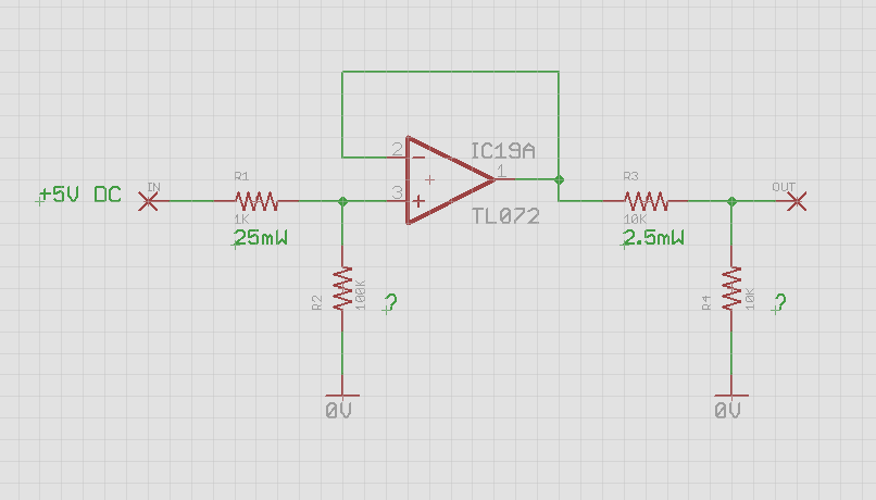
I'm using the standard equation P = (V^2)/R to calculate resistor wattage.
How do I calculate the required wattage of the resistors to Ground in the above image (R2 & R4) - or in other circuits using a 2x R divider?

Hope that makes sense, thanks.
 

Same formula. In your schematic you can ignore the current flowing into the '+' pin of the TL072 and calculate the power dissipated using Ohms law for R1 and R2 (hint: calculate the voltage across each to do this).

The amplifier is wired for unity gain so assuming it has sufficient voltage on it's supply pins, the output voltage will be the same as the input voltage (= voltage at the '+' input you already calculated). From there you can work out the voltage across R3 and R4 and the power they dissipate.

Brian.
 

The power numbers annotated in the circuit are not correct. The power dissipation is P = (V^2)/R, but you need to calculate the voltage across each resistor. It's e.g. 49.5 mV corresponding to 2.4 µW for the 1 k resistor.
 
  • Like
Reactions: juz_ad

    juz_ad

    Points: 2
    Helpful Answer Positive Rating
find the current thru the resistor then find wattage using basic formula.

p =i^2 *R..

1/4 or 1/2 w resistor is enough for your ckt
 

Hope nobody minds me revisiting this thread. I think the mistake I was making was using the Voltage *into* the Resistor - not the Voltage *across* the Resistor.

If anyone has a chance to check the Power ratings in the 2 examples below so I know I'm understanding the calculation - it would be a help and appreciated.

wattage_01.png

Thanks :thumbsup:
 

Your wattage figures appear to be right on. However from a practical point of view, your second circuit would have an output of -24v from the op-amp. But the TL072 is only built for a maximum of +/-18v power supply rails. I suppose with a ground offset toward the positive side of the +/-18v supply rails you might be able to have this condition, but it would a very non-standard circuit.
 
  • Like
Reactions: juz_ad

    juz_ad

    Points: 2
    Helpful Answer Positive Rating
Status
Not open for further replies.

Part and Inventory Search

Welcome to EDABoard.com

Sponsor

Back
Top