Continue to Site

Welcome to EDAboard.com

Welcome to our site! EDAboard.com is an international Electronics Discussion Forum focused on EDA software, circuits, schematics, books, theory, papers, asic, pld, 8051, DSP, Network, RF, Analog Design, PCB, Service Manuals... and a whole lot more! To participate you need to register. Registration is free. Click here to register now.

How to implement V/f control of 3 phase acim by arduino UNO

Status
Not open for further replies.

mobinmk

Full Member level 2
Joined
May 27, 2010
Messages
140
Helped
4
Reputation
8
Reaction score
4
Trophy points
1,298
Location
Kollam (Quilon),kerala, India
Activity points
2,484
hi frnds

i wan to make v/f control of 3phase acim

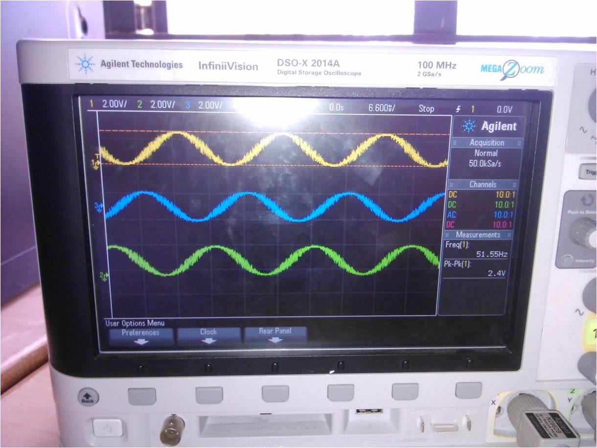
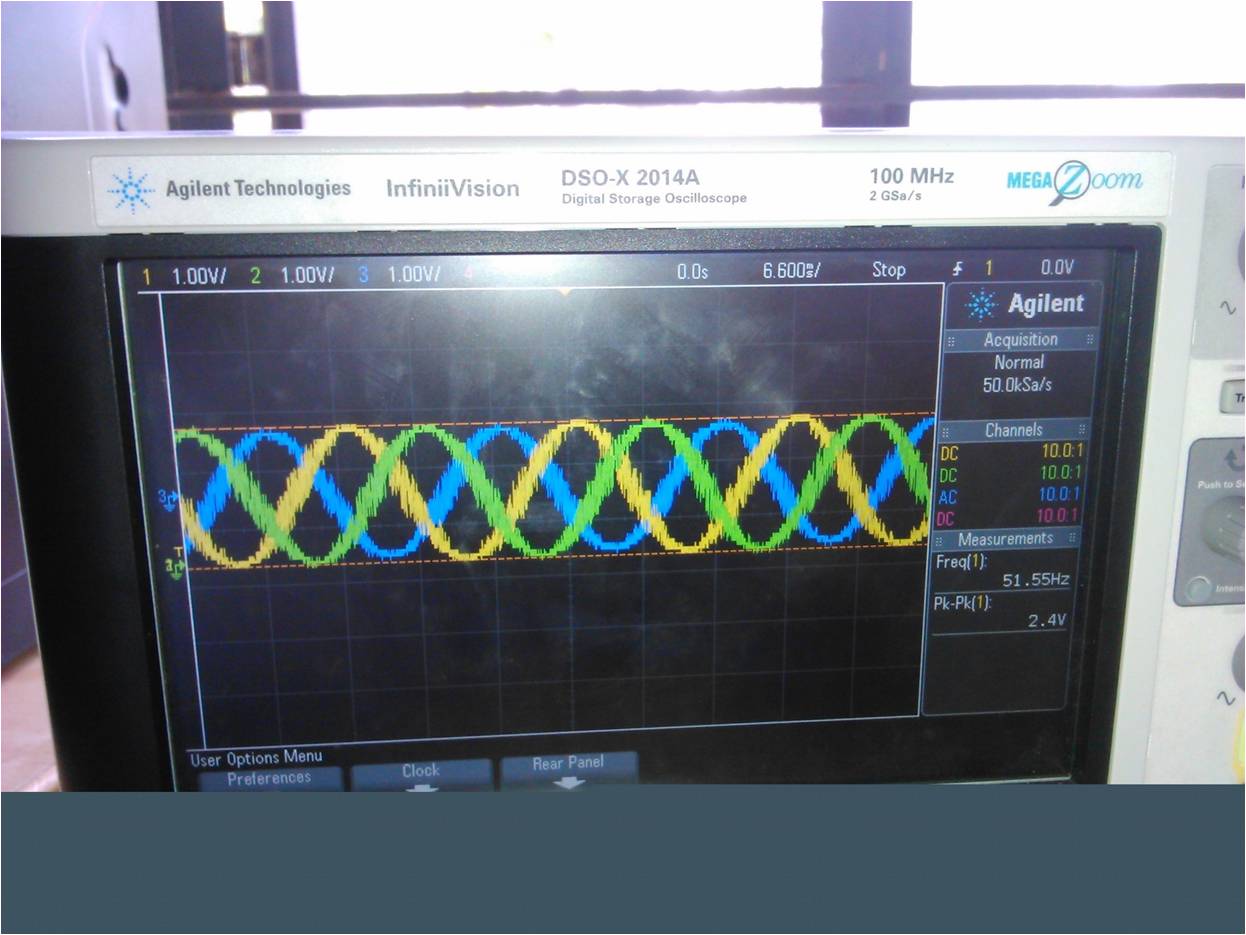
successfuly i generate 3 phase sine wave, which frequency can vary frm 1hz to 1023hz

using 3 phase DDS by sine lookup table, timer,interrupt.

now i wana to implement V/F

i attached my program

Code C - [expand]
1
2
3
4
5
6
7
8
9
10
11
12
13
14
15
16
17
18
19
20
21
22
23
24
25
26
27
28
29
30
31
32
33
34
35
36
37
38
39
40
41
42
43
44
45
46
47
48
49
50
51
52
53
54
55
56
57
58
59
60
61
62
63
64
65
66
67
68
69
70
71
72
73
74
75
76
77
78
79
80
81
82
83
84
85
86
87
88
89
90
91
92
93
94
95
96
97
98
99
100
101
102
103
104
105
106
107
108
109
110
111
112
113
114
115
116
117
118
119
120
121
122
123
124
125
126
127
128
129
130
131
132
133
134
135
136
137
138
139
140
141
142
143
144
145
/****************************************************************** 
 * DDS-sinewave - 3phase 
  *   
   ******************************************************************/ 
 
 
#include "avr/pgmspace.h" 
#include "avr/io.h" 
PROGMEM  prog_uchar sine256[] = 
{
  127,130,133,136,139,143,146,149,152,155,158,161,164,167,170,173,176,178,181,184,187,190,192,195,198,200,203,205,208,210,
 212,215,217,219,221,223,225,227,229,231,233,234,236,238,239,240,242,243,244,245,247,248,249,249,250,251,252,252,253,
253,253,254,254,254,254,254,254,254,253,253,253,252,252,251,250,249,249,248,247,245,244,243,242,240,239,238,236,234,
233,231,229,227,225,223,221,219,217,215,212,210,208,205,203,200,198,195,192,190,187,184,181,178,176,173,170,167,164,
161,158,155,152,149,146,143,139,136,133,130,127,124,121,118,115,111,108,105,102,99,96,93,90,87,84,81,78,76,73,70,67,64,
62,59,56,54,51,49,46,44,42,39,37,35,33,31,29,27,25,23,21,20,18,16,15,14,12,11,10,9,7,6,5,5,4,3,2,2,1,1,1,0,0,0,0,0,0,0,1,1,1,2,
2,3,4,5,5,6,7,9,10,11,12,14,15,16,18,20,21,23,25,27,29,31,33,35,37,39,42,44,46,49,51,54,56,59,62,64,67,70,73,76,78,81,84,87,
90,93,96,99,102,105,108,111,115,118,121,124
 
};
 
 
#define cbi(sfr, bit) (_SFR_BYTE(sfr) &= ~_BV(bit))
#define sbi(sfr, bit) (_SFR_BYTE(sfr) |= _BV(bit)) 
#define PWM_OUT_1 11  // PWM output on pin 11 
#define PWM_OUT_2 10  // PWM output on pin 10 
#define PWM_OUT_3 9  // PWM output on pin 9 
#define LED_PIN  13  // LED status on pin 13 
#define TEST_PIN 7  // Scope trigger on pin 7 
#define POTEN_IN 0  // Potentiometer on pin 0 
#define OFFSET_1 85  // Offset for second-phase
#define OFFSET_2 170  // Offset for third-phase  
 
      double dfreq; 
      const double refclk = 31376.6;  // measured 
      const uint64_t twoTo32 = pow(2, 32); // compute value at startup and use as constant 
      
      
      // variables used inside interrupt service declared as voilatile 
      volatile uint8_t icnt;   // var inside interrupt 
      volatile uint8_t icnt1;   // var inside interrupt 
      volatile uint8_t c4ms;   // counter incremented every 4ms 
      volatile uint32_t phase_accum;  // pahse accumulator 
      volatile uint32_t tword_m;  // dds tuning word m 


   void setup()
   {  
     pinMode(LED_PIN, OUTPUT); 
     // sets the digital pin as output  
     Serial.begin(115200);   // connect to the serial port   
     Serial.println("DDS Test");    
     
      pinMode(TEST_PIN, OUTPUT);         // sets the digital pin as output  
      pinMode(PWM_OUT_1, OUTPUT);       // PWM output / frequency output   
      pinMode(PWM_OUT_2, OUTPUT);       // PWM output / frequency output   
      pinMode(PWM_OUT_3, OUTPUT);       // PWM output / frequency output 
      
     // Setup the timers   
     setup_timer1();   
     setup_timer2(); 
     
       // disable interrupts to avoid timing distortion   
       cbi (TIMSK0, TOIE0);             // disable Timer0 !!! delay() is now not available   
       sbi (TIMSK2, TOIE2);             // enable Timer2 Interrupt  
    dfreq = 1000.0;                // initial output frequency = 1000.0 Hz   
    tword_m = twoTo32 * dfreq / refclk;       // calulate DDS new tuning word  
  } 
  
  
  void loop() 
  {   
    if (c4ms > 250)                // timer / wait for a full second   
    {     
      c4ms = 0;    
      dfreq = analogRead(POTEN_IN);        // read Poti on analog pin 0 to adjust output frequency from 0..1023 Hz  
      cbi (TIMSK2, TOIE2);            // disble Timer2 Interrupt    
      tword_m = twoTo32 * dfreq / refclk;       // calulate DDS new tuning word     
      sbi (TIMSK2, TOIE2);            // enable Timer2 Interrupt   
      Serial.print(dfreq);     
      Serial.print("  ");     
      Serial.println(tword_m);  
    } 
  } 
  
  
   // timer1 setup 
 // set prscaler to 1, PWM mode to phase correct PWM,  16000000/512 = 31.25kHz clock  
    void setup_timer1(void) 
    {   
      // Timer1 Clock Prescaler to : 1   
      sbi (TCCR1B, CS10);   
      cbi (TCCR1B, CS11);   
      cbi (TCCR1B, CS12);  
      // Timer0 PWM Mode set to Phase Correct PWM   
      cbi (TCCR1A, COM1A0);           // clear Compare Match   
      sbi (TCCR1A, COM1A1);   
      cbi (TCCR1A, COM1B0);           // clear Compare Match   
      sbi (TCCR1A, COM1B1);  
      
      sbi (TCCR1A, WGM10);            // Mode 1  / Phase Correct PWM   
      cbi (TCCR1A, WGM11);   
      cbi (TCCR1B, WGM12);   
      cbi (TCCR1B, WGM13); 
    }  
    
    
    // timer2 setup
    // set prscaler to 1, PWM mode to phase correct PWM,  16000000/512 = 31.25kHz clock 
    void setup_timer2(void) 
    {   
      // Timer2 Clock Prescaler to : 1   
      sbi (TCCR2B, CS20);   
      cbi (TCCR2B, CS21);   
      cbi (TCCR2B, CS22);  
  // Timer2 PWM Mode set to Phase Correct PWM   
    cbi (TCCR2A, COM2A0);           // clear Compare Match   
    sbi (TCCR2A, COM2A1);   
    sbi (TCCR2A, WGM20);            // Mode 1  / Phase Correct PWM   
    cbi (TCCR2A, WGM21);   
    cbi (TCCR2B, WGM22); 
    
    }   
    
//****************************************************************** 
// Timer2 Interrupt Service at 31.25kHz = 32us 
// this is the timebase REFCLOCK for the DDS generator 
// FOUT = (M (REFCLK)) / (2 exp 32) 
// runtime : 8 microseconds ( inclusive push and pop) 
ISR(TIMER2_OVF_vect) 
{   
  sbi(PORTD, TEST_PIN);           // Test / set PORTD,TEST_PIN high to observe timing with a oscope  
  phase_accum += tword_m;          // soft DDS, phase accu with 32 bits   
  icnt = phase_accum >> 24;          // use upper 8 bits for phase accu as frequency information  
  OCR2A = pgm_read_byte_near(sine256 + icnt);  // read value fron ROM sine table and send to PWM DAC  
  OCR1A = pgm_read_byte_near(sine256 + (uint8_t)(icnt + OFFSET_1));  
  OCR1B = pgm_read_byte_near(sine256 + (uint8_t)(icnt + OFFSET_2));  
  if (icnt1++ == 125)             // increment variable c4ms every 4 milliseconds   
      {     
        c4ms++;     
      icnt1 = 0;   
      }   
  cbi(PORTD, TEST_PIN);           // reset PORTD,TEST_PIN 
}


pls share your knowledgzzz...

regards

mobin
 
Last edited by a moderator:

Status
Not open for further replies.

Part and Inventory Search

Welcome to EDABoard.com

Sponsor

Back
Top