Continue to Site

Welcome to EDAboard.com

Welcome to our site! EDAboard.com is an international Electronics Discussion Forum focused on EDA software, circuits, schematics, books, theory, papers, asic, pld, 8051, DSP, Network, RF, Analog Design, PCB, Service Manuals... and a whole lot more! To participate you need to register. Registration is free. Click here to register now.

[SOLVED] Verilog Variable Slicing

Status
Not open for further replies.

keyboardcowboy

Member level 2
Joined
Mar 4, 2010
Messages
42
Helped
0
Reputation
0
Reaction score
0
Trophy points
1,286
Activity points
1,612
Is it possible to to do this in any way in verilog

1. Define a 1024 bit reg

Code:
reg [1023:0] ABC;

2: fill this reg using another 32-bit reg which varies

for example
Code:
ABC[31:0] = input;
                  ABC[64:32] = input2;

in other words

Code:
 ABC[variable:variable] = input;

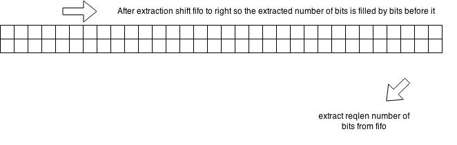
variable data slicing
 

Yes. It is possible in the same way you have shown. Either using assign statements or within an always block..
 

Yes. It is possible in the same way you have shown. Either using assign statements or within an always block..

I have tried doing it using VCS, but get an error saying they have to be constant during compile
 

Could you post your code (section of code)?
 

As long as the width stays the same you can slice like this


Code Verilog - [expand]
1
2
3
4
5
6
7
8
9
10
11
12
13
14
assign abc[lsb +:32] = input;
// if there are multiple inputs you wish to assign to different slices of abc I suggest making input an array of inputs.
wire [31:0] input [0:31];
 
// The assign the array using a for loop (to save typing)
generate genvar i;
for (i=0;i<32;i=i+1) begin
  assign abc[32*i +:32] = input[i];
  // i.e.
  // assign abc[31:0] =input[0];
  // assign abc[63:32] =input[1];
  // ...
end
endgenerate


Varying both the msb and lsb of a slice is not allowed (not sure if that has changed with System Verilog).
 

My code

xCBRMdD.jpg

As long as the width stays the same you can slice like this


Code Verilog - [expand]
1
2
3
4
5
6
7
8
9
10
// The assign the array using a for loop (to save typing)
generate genvar i;
for (i=0;i<32;i=i+1) begin
  assign abc[32*i +:32] = input[i];
  // i.e.
  // assign abc[31:0] =input[0];
  // assign abc[63:32] =input[1];
  // ...
end
endgenerate


Varying both the msb and lsb of a slice is not allowed (not sure if that has changed with System Verilog).

Yes, this is what I am trying to do. The input is is changing 32 bit random integer so instead of


Code Verilog - [expand]
1
2
// assign abc[31:0] =input[0];
  // assign abc[63:32] =input[1];


this is what i want to do


Code Verilog - [expand]
1
2
3
4
// assign abc[31:0] =input;
  // assign abc[63:32] =input;
 
 // input changes randomly


but you mentioned system verilog so I assume this is not possible in verilog??

This is what i want to achieve ..

A 32x32 Fifo is filled with random [32:0] reg
Request is made for random widths of bits which needs to be extracted from the fifo, this request is random from 0 to 15. for example if it is 5 then I need to push out the 5 bits from the bottom row of the fifo and shift the entire fifo 5 to the right so that the extracted bits are distracted, and the 5 bits from the row above are joined with the row below in the beginning. What I was trying to do was

instead of implementing the fifo as

Code:
reg [31:0] fifo[31:0]

I am trying to make it like

Code:
reg [1023:0] fifo
in this way i can just use the verilog shift operators to shift the entire fifo,
but I am having problems filling the fifo with incoming data
 
Last edited by a moderator:

You seem to be thinking more like Verilog as software and not Verilog as representing hardware.

You need to understand the underlying hardware connections to allow for the various shift by 5 options to understand what every possible word position looks like.

The write side of the FIFO from input is just a demultiplex, the only signal you should be messing with is the FIFO write strobe, not the data.

- - - Updated - - -

A 32x32 Fifo is filled with random [32:0] reg
Request is made for random widths of bits which needs to be extracted from the fifo, this request is random from 0 to 15. for example if it is 5 then I need to push out the 5 bits from the bottom row of the fifo and shift the entire fifo 5 to the right so that the extracted bits are distracted, and the 5 bits from the row above are joined with the row below in the beginning.
This description is hard to follow, I think a well thought out block diagram and some examples of the data manipulations required than a description of what you've tried to implement would be better. For all I can tell you're taking a bad approach and touting it as the only way to implement your function.

IMO if the solution involves complex difficult to write code then you're taking the wrong approach from the start and it's time to go back and look at the architecture of the design.
 

Ok let me give it another shot, block diagram would be a bit harder to do.

1. I have a FIFO which has a width 0f 32 and height of 32
2. The FIFO has a Pushin input (0 or 1) and datain input (32 bit random)
3. On every Pushin the FIFO stores the 32 bit datain which changes with each pushin

4. The FIFO also has reqin (0 or 1) and reqlen (0 to 15) both random
5. On each reqin, reqlen number of bits are to be pushed out from the fifo, and the fifo needs to be readjusted so that the number of bits that have been pushed out are replaced with bits before it


In simple terms, traditionally a FIFO takes a fixed size input and outputs a fixed size, I want to implement a Fifo which takes a fixed input but outputs a variable length data depending on reqlen variable
 

First of all this isn't anything like a FIFO so you should probably stop calling it that. I would probably refer to it as a data width conversion buffer.

Okay now we have some small tidbit of information, but hardly what could be called a specification.

What is the ingress rate?
What is the egress rate? (they can't be equal as there is the stipulation that the number of bits read can vary)
How does the reqlen map to number of bits? This is not clearly defined.
What is the relationship between the two requests?

Actually hardly anything about your specification is well defined except maybe the following:
32-bit input
two output requests
reqlen that can have the values of 0-15

Oh, boy that explains everything!


Now if there is enough time to serialize the output data that is probably one of the easiest ways to change the width. Serialize the data read and only deserialize the number of bits specified by the reqlen. On the next request you just deserialize the next set of bits. This is very easy to do and doesn't require complex barrel shifting operations or variable bit slicing (which isn't possible to do in hardware).

If you don't have the time to serialize then you're might be stuck with a barrel shifter to align the output of a n-bit chunk of the 1024-bits to the output. This will require a lot of pipelining.
 

Status
Not open for further replies.

Part and Inventory Search

Welcome to EDABoard.com

Sponsor

Back
Top