Continue to Site

Welcome to EDAboard.com

Welcome to our site! EDAboard.com is an international Electronics Discussion Forum focused on EDA software, circuits, schematics, books, theory, papers, asic, pld, 8051, DSP, Network, RF, Analog Design, PCB, Service Manuals... and a whole lot more! To participate you need to register. Registration is free. Click here to register now.

Pulse stretcher using CMOS 4000 series for detecting data for MAX232 in serial com

Status
Not open for further replies.

SparkyChem

Member level 3
Joined
Apr 22, 2010
Messages
57
Helped
0
Reputation
0
Reaction score
0
Trophy points
1,286
Location
Lima, Peru
Activity points
2,084
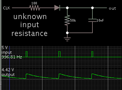
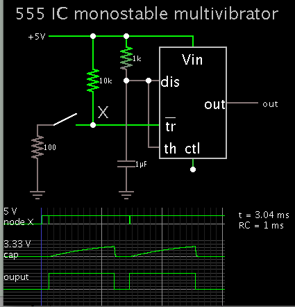
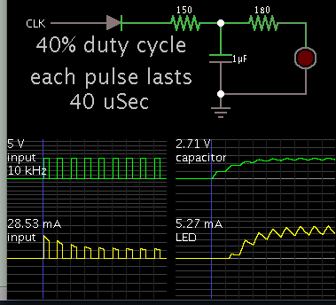
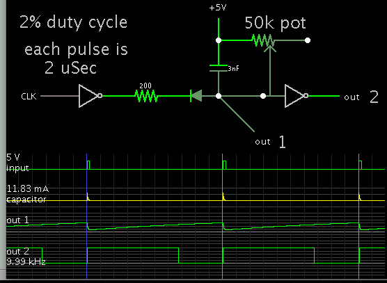
Hello, i need help on designing a proper circuit for adding status leds using a MAX232 when connected to a PIC. i tried the usual setting tying leds from the TX and RX from the uC but the problem is that they dont lid correctly, i've been told that using a pulse stretcher would be a more efficient solution to this so i could see the bits more properly when they are being transmitted during serial communication. Can somebody would share to me a simple but effective CMOS 4000 series pulse stretcher that i can use to do this?. Thanks in advance.
 

MAX232 data is positive logic bipolar with a threshold of 2 diode drops or 1.3 like TTL but can may exceed +/- 5V

HC CMOS is normally Vccx/2

Do you know how to limit the signal for 5V logic without loading RS232?
Do you know what a one shot IC is?" It can be as simple as a diode cap + slow decay R + buffer or a dual 1shot IC.

now search

Are you referring to a monostable multivibrator? i think using two NOR gates can be used with this but i dont know about the diode you cap plus R. i think for better visualization maybe you can give me some examples of what you meant. Thanks in advance.
 

i think using two NOR gates can be used with this but i dont know about the diode you cap plus R.

I have a hunch this is the method SunnySkyguy is referring to.

The capacitor charges quickly from an incoming pulse. Then it discharges slowly through a resistor.


Feed the output to a logic gate.

You must find the proper capacitor value through experimentation.

The logic gate probably has its own internal input resistance. (A typical value is 1M ohm.) This could take the place of the discharge resistor.

From what i understood i can try using a monostable multivibrator. Would this kind of circuit work?.

PIT1msW.png


i can try it as i have a CD4049 at hand, but my major concern is the minimum trigger pulse coming from the PIC, would less than 250 ns be enough as an input for this circuit?, and how about the output? can it be pulse stretched to let's say up to 1ms?. I think R1 value can be just 1k?. is the time constant for this monostable multivibrator T = 0.8RC + Trigger ?

It would be very helpful if somebody could simulate this circuit but wouldn't load the RS232.

It is said that a main disadvantage of monostable multivibrators is that the time between the application of the next trigger pulse T has to be greater than the RC time constant of the circuit, that being said, would this be recommended for my application?.
 

Have you considered the 555 timer IC for your pulse stretcher?

Operating as a monostable multivibrator:


The caption at lower right states the delay as 1 mSec.
The simulation covers 3 mSec.

The switch was pressed for a couple hundred nSec, about the time you specified.
 

Have you considered the 555 timer IC for your pulse stretcher?

Operating as a monostable multivibrator:


The caption at lower right states the delay as 1 mSec.
The simulation covers 3 mSec.

The switch was pressed for a couple hundred nSec, about the time you specified.

I also noted that using a 555 timer could do that work, but i note that there is a volatge drop to 3.3v in the output, would this happen with the method you posted earlier? i mean the diode plus the RC circuit?. If possible i would like to stick with the individual logic gates of the 4000 family, but my problem is if there would be a voltage drop like the 555.

I found that a monostable multivibrator can be made with NAND gates, but would this be more effective than using a 555 or the NOR gates?

ZedJbQl.png
 

I also noted that using a 555 timer could do that work, but i note that there is a volatge drop to 3.3v in the output, would this happen with the method you posted earlier? i mean the diode plus the RC circuit?. If possible i would like to stick with the individual logic gates of the 4000 family, but my problem is if there would be a voltage drop like the 555.

The 555 output goes to supply V, or close to it. (I guess I should have commanded the bottom scope trace to label the voltage highest reading.)

The capacitor charges to 2/3 of supply V. That causes the timing cycle to end. That is why 3.3V is the high reading on the scope trace.

Did you try your schematic in simulation?

Logic gates do not operate by hysteresis by themselves. We are looking at conceptual circuits which require the capacitor to charge instantly, from a brief pulse. This is not easy to achieve. Moreover it is not easy to adjust the timing cycle. As you notice, the diode causes a 0.6V drop.

The 555, on the other hand, has its own internal hysteresis envelope. It receives a pulse (perhaps very brief), then it starts charging the capacitor gradually. Its operation is predictable. The timing cycle is easy to adjust.

Yes i tried the schematic in simulation and it works but i dont get why do you left ctl pin unconnected. Shouldn't be connected to a 0.01 uF capacitor?.

Although i appreciate your efforts for giving to me a hint on how to do this with a 555 time i need to do this with 4000 series. That being said, wouldn't be a better option for a monostable using a CD4098, CD4538 or with CD4047?.
 

There are a few considerations for a RS232 to CMOS data indicator

RS232 ( or +/-3 to +/-15) needs to be made unipolar for CMOS using internal ESD diodes.
Film cap is preferred for low leakage Cap and RC > 0.1second
LED current and ON time are user choices in design.

5158129600_1425182048.jpg


PLay with sim. press on switch.
 
Yes i tried the schematic in simulation and it works but i dont get why do you left ctl pin unconnected. Shouldn't be connected to a 0.01 uF capacitor?.

Yes, it is common to add the capacitor at the ctl pin. The simulator defaults to leaving it unconnected, to make things simple.

Although i appreciate your efforts for giving to me a hint on how to do this with a 555 time i need to do this with 4000 series. That being said, wouldn't be a better option for a monostable using a CD4098, CD4538 or with CD4047?.

Those are designated as monostables. I imagine they will work, similar to a 555.

You'll want to check whether their output impedance is low enough, and can produce an Ampere level that will drive your intended load.

As for the 555, it can provide 200 mA.
 
There are a few considerations for a RS232 to CMOS data indicator

RS232 ( or +/-3 to +/-15) needs to be made unipolar for CMOS using internal ESD diodes.
Film cap is preferred for low leakage Cap and RC > 0.1second
LED current and ON time are user choices in design.

5158129600_1425182048.jpg


PLay with sim. press on switch.

Thanks it was very illustrative. This circuit works as mentioned but the problem i have with it although does indeed stretch the pulse, it causes the LED to stay lit all the time. Not surprisingly as when the new pulse comes in there is little time for the cap to discharge and turn off the LED. I understand by changing resistor and cap values i can change the constant but it doesn't help much for the intended purpose.

Instead of using this approach would it be a way to slow down the input frequency coming from the RS232 signal to its half?. Let's say, like this:

\[output frequency =\frac{Input frequency}{2}\]​

then that way it would let enough time for the signal to be seen by the eyes on the LED.

Yes, it is common to add the capacitor at the ctl pin. The simulator defaults to leaving it unconnected, to make things simple.


Those are designated as monostables. I imagine they will work, similar to a 555.

You'll want to check whether their output impedance is low enough, and can produce an Ampere level that will drive your intended load.

As for the 555, it can provide 200 mA.

I tried in simulator those and it work much like 555 but as mentioned above i'm thinking in changing the approach. Is it possible to reduce the frequency using logic gates plus other components?.
 
Last edited:

TIs it possible to reduce the frequency using logic gates plus other components?.

To answer your question, a single flip flop is the classic method to divide an incoming pulse train by 2.

The D type is simple and easy to wire for doing this.

======================================

Your purpose is not too different from a logic probe. If you look at some schematics you might find one which lengthens a brief pulse, so that human eyes can observe it.

I just realized that for serial port (232) working at 9600 baud, 8 data bits, no parity and 1-stop bit which is where i intend to use this circuit would be an equivalent to 4800 Hz. In order for the human eyes to perceive the train pulse would require to lower the frequency to at least 12 Hz.

Thus:

\[4800 Hz=\frac{12 Hz}{N}\\
N=\frac{12}{4800}= \frac{1}{400}\\\]​

If i were to use a D type flip flop for this purpose would meant to stack of several flip flops in order to achieve the desired 400 or something closer to that i.e dividing by-512 would be 9. That being said, isn't there a more efficient way to achieve this?.
 

If you have a series of pulses to detect, then they might be sufficient to power a simple diode and capacitor, so as to light an led continuously.


This method 'steals' several mA from the signal. If that interferes with proper operation, then reduce the capacitor value, make it a sample-and-hold to bias a transistor, and power the led that way.

By doing the method you mentioned would need to add an op amp and a transistor. Can you make the simulation?. Again, i think that the key in this circuit is to lower the train pulse from a 48 kHz (roughly 21 us) to somewhere between 65 ms to 85 ms or higher time.

Using an op amp means we're switching from digital to analog, from what i understand is that there is no way to do this resorting only with logic gates right?.
 

There are a few considerations for a RS232 to CMOS data indicator

RS232 ( or +/-3 to +/-15) needs to be made unipolar for CMOS using internal ESD diodes.
Film cap is preferred for low leakage Cap and RC > 0.1second
LED current and ON time are user choices in design.

5158129600_1425182048.jpg


PLay with sim. press on switch.

If this doesn't work for your LED , you are doing something wrong like using O.C. Logic with no pullup. schottky diodes are preferred to minimize loss in margin.

What are you logic levels?

Typically when one needs a precision pulse stretcher , we call it a 1-shot which can be retrigerable or not. In this case you want it retriggerable.

The technical name for the IC is a Monostable Multivibrator and there are dozens.

Here's one
http://cds.linear.com/docs/en/datasheet/69931234fb.pdf

Oh BTW all logic chips are "analog" devices under the hood, and can be used in many analog ways. Oscillators, analog switches etc.
 

An op amp is not always necessary.

It could help to spend time experimenting with logic gates. They can be persuaded to do a few of the same things for which we might ordinarily select an op amp. Example, act as a comparator, because Vcc/2 is an automatic threshold which, if crossed, causes the output to change state.

It is possible to operate a logic gate with hysteresis as well. (I believe your post #7 schematic does that.)

Looking back to your schematic in post #5, I made a similar simulation. It does not need to steal current from the input signal.


Its operating principle is similar to SunnySkyguy's post #10.

All devices are powered by 5V.
 

...If possible i would like to stick with the individual logic gates of the 4000 family, but my problem is if there would be a voltage drop like the 555.

I found that a monostable multivibrator can be made with NAND gates, but would this be more effective than using a 555 or the NOR gates?

ZedJbQl.png

CDxxxx series is fine with Any logic...
Above Nand is non-retriggerable.

My cct with diode RC, was Retriggerable.
It works.
 

If this doesn't work for your LED , you are doing something wrong like using O.C. Logic with no pullup. schottky diodes are preferred to minimize loss in margin.

What are you logic levels?

Typically when one needs a precision pulse stretcher , we call it a 1-shot which can be retrigerable or not. In this case you want it retriggerable.

The technical name for the IC is a Monostable Multivibrator and there are dozens.

Here's one
http://cds.linear.com/docs/en/datasheet/69931234fb.pdf

The circuit you proposed it does work, i'm not objecting that. The problem is that when i tried to use it, it didn't worked the way i thought it would.

Let me explain, when i originally posted this question i thought that using a pulse stretcher would help to solve the problem of visualizing a LED when getting 232 signals, but by using this method turns on the LED at the expense of reducing the low level.

What i was looking for was to slow down the train pulse at a rate that would give enough time for the LED to switch between states so eyes could see it, unfortunately this cannot be achieved by using a pulse stretcher, then i reformulated my question so the approach could be different.

My current aim is to reduce the frequency, so i'm looking for help with this.

Oh BTW all logic chips are "analog" devices under the hood, and can be used in many analog ways. Oscillators, analog switches etc.

I am aware of that, maybe my definition was superficial to you, but when you look at beginner's book that's usually the way how we 'aspiring technicians' see it.
 

Status
Not open for further replies.

Similar threads

Part and Inventory Search

Welcome to EDABoard.com

Sponsor

Back
Top