Continue to Site

Welcome to EDAboard.com

Welcome to our site! EDAboard.com is an international Electronics Discussion Forum focused on EDA software, circuits, schematics, books, theory, papers, asic, pld, 8051, DSP, Network, RF, Analog Design, PCB, Service Manuals... and a whole lot more! To participate you need to register. Registration is free. Click here to register now.

[PIC] Help senzing values higher than vdd using mikrobasic in PIC16F676

Status
Not open for further replies.

SparkyChem

Member level 3
Joined
Apr 22, 2010
Messages
57
Helped
0
Reputation
0
Reaction score
0
Trophy points
1,286
Location
Lima, Peru
Activity points
2,084
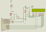
Hello there, i have this mikrobasic code but my problem is that i don't know how to modify it so it can work with voltages higher than 5 volts. The uC i'm using is PIC16F676 which has an internal ADC module.

Maybe if i make Vref different than Vdd and i do tie that pin to a different reference i.e 1.25V and then using an op amp to downsize the voltage from let's say 9volts to 900mV and then using that signal from the output side of an op amp as the one which would then be measured by the ADC module. Would that be okay?. i wonder if doing that would mean losing accuracy in the adc conversion process.

i'm sorry i don't know what to do. Any help would be appreciated, thanks in advance.

Code:
program F676_exp
' Declarations section
'******************************************************
dim LCD_RS as sbit at RC4_bit ' Lcd
LCD_EN as sbit at RC5_bit
LCD_D4 as sbit at RC3_bit
LCD_D5 as sbit at RC2_bit
LCD_D6 as sbit at RC1_bit
LCD_D7 as sbit at RC0_bit
LCD_RS_Direction as sbit at TRISC4_bit
LCD_EN_Direction as sbit at TRISC5_bit
LCD_D4_Direction as sbit at TRISC3_bit
LCD_D5_Direction as sbit at TRISC2_bit
LCD_D6_Direction as sbit at TRISC1_bit
LCD_D7_Direction as sbit at TRISC0_bit ' LCD
dim text as string [16]   ' text string
dim ch, adc_rd as word    ' ch, adc_rd word
dim tlong as word     ' tlong, longword
sub procedure settings
CMCON=7
ANSEL=%00000001
ADCON1=%00110000
ADCON0=%10000001
TRISA=%000001
INTCON = 0                ' all interrupts disabled
TRISC = 0   ' PORTC is output
end sub
main:
'   Main program
settings
Lcd_Init()                ' LCD
Lcd_Cmd(_LCD_CURSOR_OFF)  ' LCD (off)
Lcd_Cmd(_LCD_CLEAR)       ' LCD command (clear LCD)
text = "mikroElektronika" ' First message
Lcd_Out(1,1,text)         ' First message, first line
text = "LCD example"      ' Second message
Lcd_Out(2,1,text)         ' Second message, second line
Delay_ms(500)
text = "Voltage="         ' Third message
while 1                   ' Loop
  adc_rd = ADC_Read(0)    ' A/D conversion. RA0 input.
  Lcd_Out(2,1,text)       ' Result second line
  tlong = adc_rd * 5000   ' Milivolt
  tlong = tlong / 1023    ' 0..1023 -> 0-5000mV
  ch = (tlong / 1000) mod 10 '
                             '
  Lcd_Chr(2,9,48+ch)      '
  Lcd_Chr_CP(".")         '
  ch = (tlong / 100) mod 10 '
  Lcd_Chr_CP(48+ch)         '
  ch = (tlong / 10) mod 10  '
  Lcd_Chr_CP(48+ch)         '
  ch = tlong mod 10         '
  Lcd_Chr_CP(48+ch)         '
  Lcd_Chr_CP("V")           ' Show "V"
  Delay_ms(1)               ' 1mS delay
wend
end.
 

What do you want to measure ? What is the range of voltage you want to measure ? Do you want to measure like DC 12V using ADC ?
 

What do you want to measure ? What is the range of voltage you want to measure ? Do you want to measure like DC 12V using ADC ?

Yeah basically its a voltmeter. The range i'm thinking is 0 to 10 volts.
 

Here I made 0 to 30V voltmeter. I compiled code for XT 4 MHz. Maybe you configured ADCONx for 8 MHz. If you want 8 MHz then compile code for HS 8 MHz. If you need XT 4 MHz then configure ADCONx properly because Proteus is giving warning related to incorrect Tad.

If you want for 0 to 10 then replace 25k resistor with 5k and in code change 30 to 10.

Edit. You also have to change +30.0V to +10.0V in Proteus.
 

Attachments

  • ADC.rar
    35.2 KB · Views: 76

Here I made 0 to 30V voltmeter. I compiled code for XT 4 MHz. Maybe you configured ADCONx for 8 MHz. If you want 8 MHz then compile code for HS 8 MHz. If you need XT 4 MHz then configure ADCONx properly because Proteus is giving warning related to incorrect Tad.

If you want for 0 to 10 then replace 25k resistor with 5k and in code change 30 to 10.

Edit. You also have to change +30.0V to +10.0V in Proteus.

I understand what you mean but can you please upload the Proteus file to take a look at the circuit?. Thanks in advance.
 

Here is the circuit and mikroBasic PIC Code. This is for 10V. Set OSC type and OSC freq properly in Project settings.


Code - [expand]
1
2
3
4
5
6
7
8
9
10
11
12
13
14
15
16
17
18
19
20
21
22
23
24
25
26
27
28
29
30
31
32
33
34
35
36
37
38
39
40
41
42
43
44
45
46
program adc
 
dim LCD_RS as sbit at RC4_bit ' Lcd
LCD_EN as sbit at RC5_bit
LCD_D4 as sbit at RC3_bit
LCD_D5 as sbit at RC2_bit
LCD_D6 as sbit at RC1_bit
LCD_D7 as sbit at RC0_bit
LCD_RS_Direction as sbit at TRISC4_bit
LCD_EN_Direction as sbit at TRISC5_bit
LCD_D4_Direction as sbit at TRISC3_bit
LCD_D5_Direction as sbit at TRISC2_bit
LCD_D6_Direction as sbit at TRISC1_bit
LCD_D7_Direction as sbit at TRISC0_bit ' LCD
 
dim text as string[23]
dim adc_rd as word
 
sub procedure settings
    CMCON = 7
    ANSEL = %00000001
    ADCON1 = %00110000
    ADCON0 = %10000001
    TRISA = %000001
    TRISC = 0
end sub
main:
 
    settings
    Lcd_Init()
    Lcd_Cmd(_LCD_CURSOR_OFF)
    Lcd_Cmd(_LCD_CLEAR)
    text = "Voltmeter"
    Lcd_Out(1,1,text)
    text = "V = "
    Lcd_Out(2,1,text)
    
    while 1
        adc_rd = ADC_Read(0)
        adc_rd = adc_rd * 10 / 1023
        Delay_ms(20)
        WordToStr(adc_rd, text)
        Ltrim(text)
        LCD_Out(2,5,text)
    wend
end


Attachments

  • adc.png
    adc.png
    46.4 KB · Views: 89

Status
Not open for further replies.

Similar threads

Part and Inventory Search

Welcome to EDABoard.com

Sponsor

Back
Top