tomeeh
Junior Member level 1
Hi,
finally I decided to show my DIY. It is a clock based on RGB strip (WS2812B) with DCF-77 receiver and automatic brightness control.
1. Idea.
Since I was a child I wanted to build an analog clock using LEDs. However, I was too lazy to use multiplexers, port replicators etc. In December 2013 a friend of mine showed me the LED bar based on WS2812B. And that was it! I’ve been always looking for something like that. Instead of complicated hardware, you can control many LEDs using one microcontroller pin. The same day I ordered the strip a started the project. Today, after 13 months I would say the project is mature so it is time to present it.
2. Requirements
The main requirement was to build a clock that is totally maintenance-free. No buttons to set the time, no buttons to dim - it should be a clock that just always shows the correct time.
a. Setting the time
I never felt comfortable with setting the clocks at home after switching to daylight saving time (CET -> CEST and vice versa). So it was pretty clear this clock has to adjust the correct time by itself. I considered GPS, Internet, but finally – because of the simplicity and good coverage in buildings – I took DCF77 (long wave time signal available in Europe).
b. brightness adjustment
Since the brightness during the day and night varies significantly, I assumed the clock must do the same. Otherwise it would be useless to have a clock with the display being too dark during the day or too bright at night.
3. Hardware
I like tiny PCBs, so it was easy to choose the microcontroller – let’s take a tiny microcontroller, to be more specific – Attiny85. It has 6 GPIOs which I used as follows:
a. Pin PB5 is a reset and remains not used in my application, since I don’t have HV programming tool, just ISP. As a programmer I took usbasp with the alternative firmware USB AVR LAB (link). I highly recommend it since beside usbasp you get an emulation of following hardware: AVRISPmkII, STK500v2, OpenOCD, JTAGICEmkII, basic oscilloscope, boundary scan interface, data logger I2C, USB-UART converter or USB-RS232/485 converter. And all of it works - of the shelf - on the usbasp hardware. I decided to set STK500v2 mode and therefore I could access the usbasp directly from the AVR Studio 4.19. The AVR Studio recognized the hardware as STK500v2. Ok; you may ask why I used old 4.19 instead of modern Atmel Studio 6. The answer is: Studio 6 is too large for me, I like tiny things…
b. Pins PB3 and PB4 are used for the external crystal 8 MHz. I was considering using the internal RC oscillator from Attiny, but the deviation was too big. The goal for the clock is the accuracy that has always to be better than 1 second; so even with synchronization it would be pretty inaccurate when internal RC was involved.
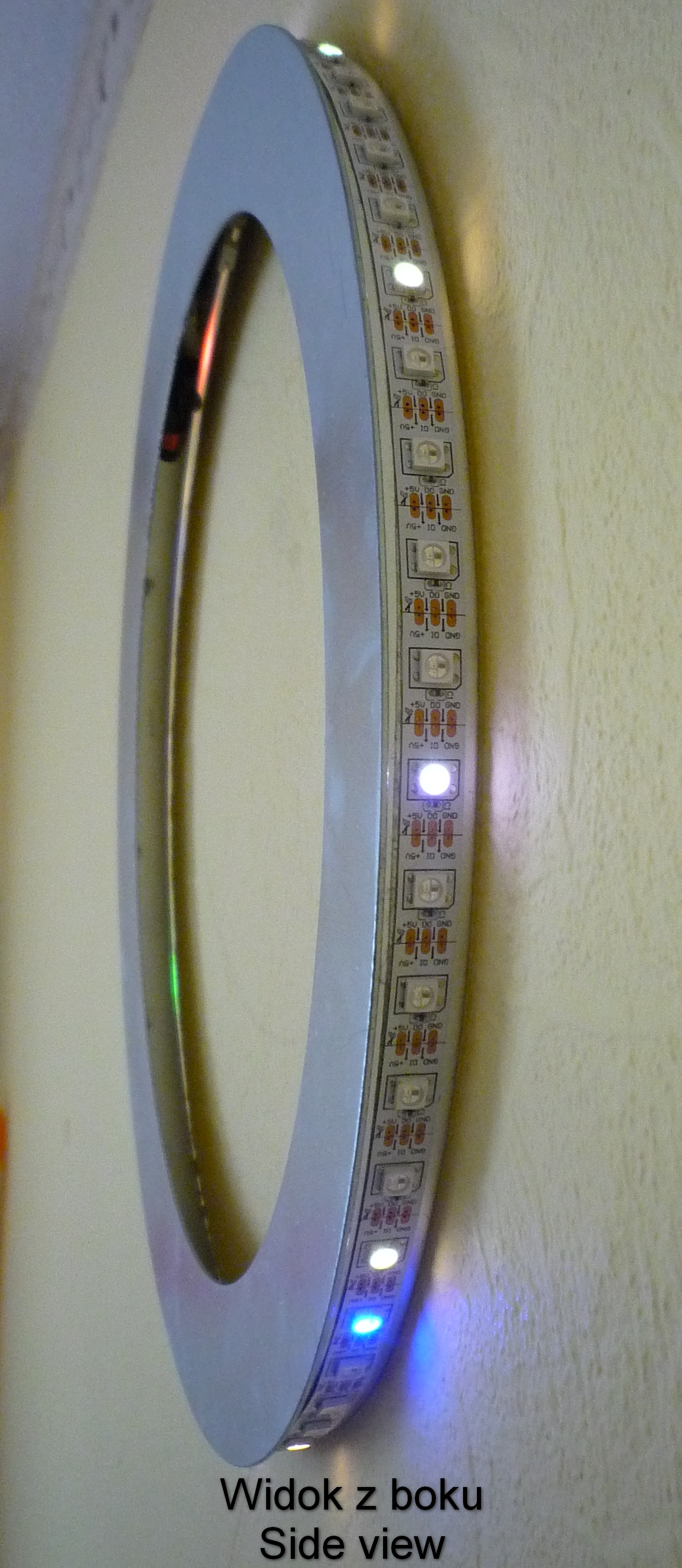
c. Pin PB1 controls the LED strip.
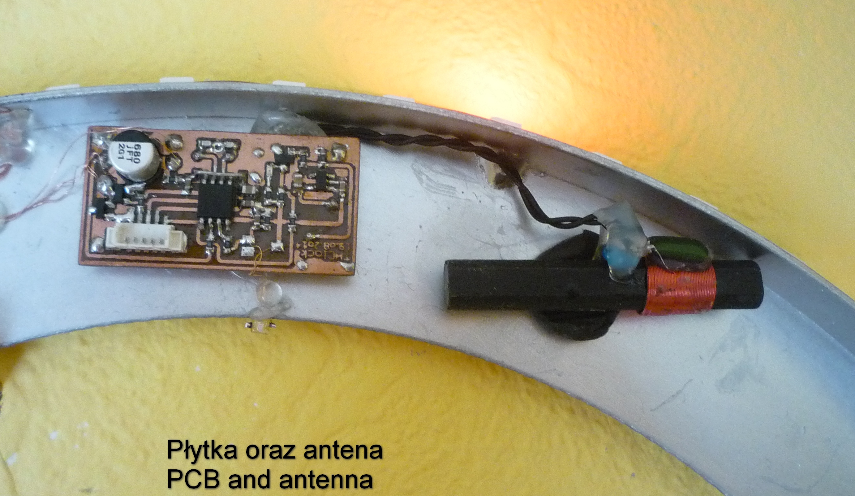
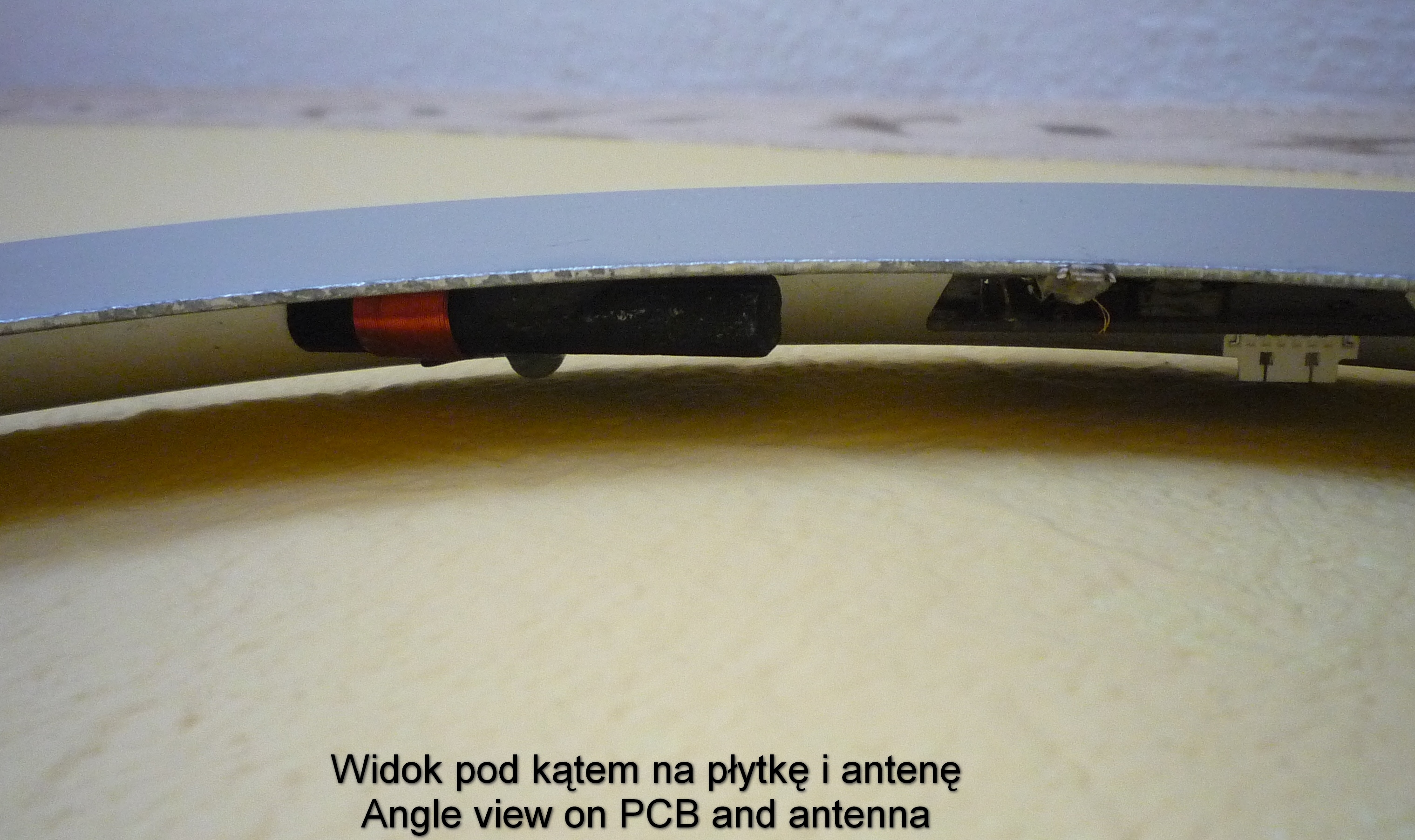
d. Pin PB0 acquires the DCF77 signal. The DCF module was re-cycled from one of my clocks. It is pretty small: 17 by 14 millimeters (0.67 x 0.55 inch). To optimize the quality of the received signal I decided to tune the ferrite antenna to hit the resonance frequency exactly at 77.50 kHz. For this, I built a second ferrite antenna and fed it with a generator 77.50 kHz. The receiving antenna was connected to a simple amplifier built using a J-FET transistor. By observing the amplitude of the received signal on the oscilloscope I found the correct capacity that had to be added to the antenna. In my case it was about 50 pF.
The DCF receiver is supplied from the 1.5 V voltage regulator (IC2).
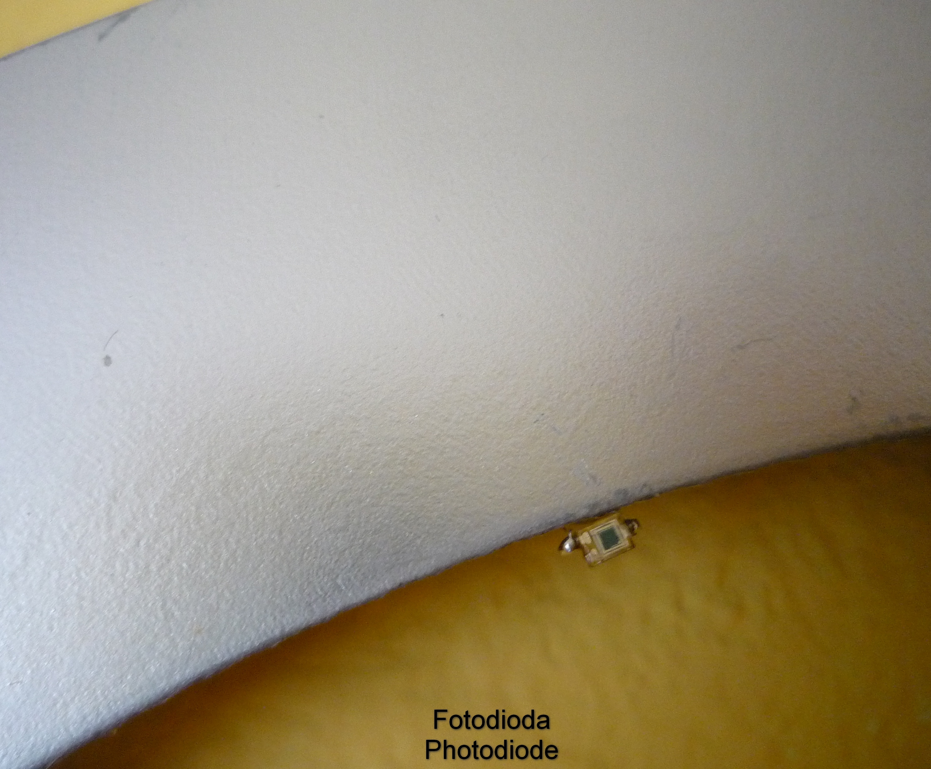
e. Pin PB2 is used as an input for the ADC. The ADC samples the photodiode in order to adjust the brightness of the LEDs.
Soon it turned out, the interference from the LEDs are too high to get a satisfactory reception of the DCF signal. Therefore I added a transistor T2 to cut the voltage to the LED strip. In this case, the PB2 is re-configured to a digital output. Driving PB2 high switches the transistor T2 off. During the normal functioning T2 never switches off, since the voltage across R5 is too low to influence T2 (Vgsth max = 0.95 V).
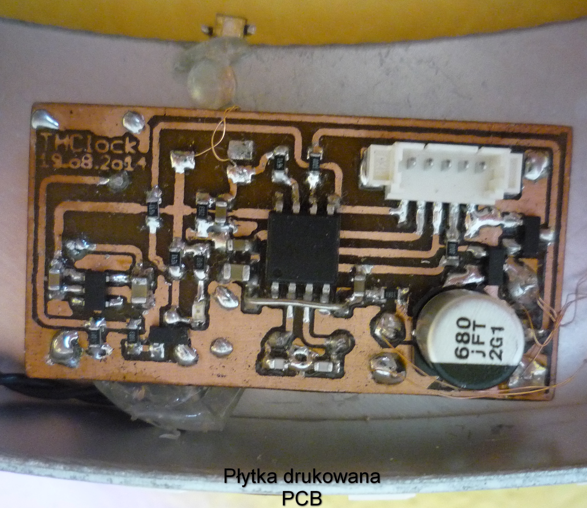
For programming of the microcontroller, a tiny connector has been used.
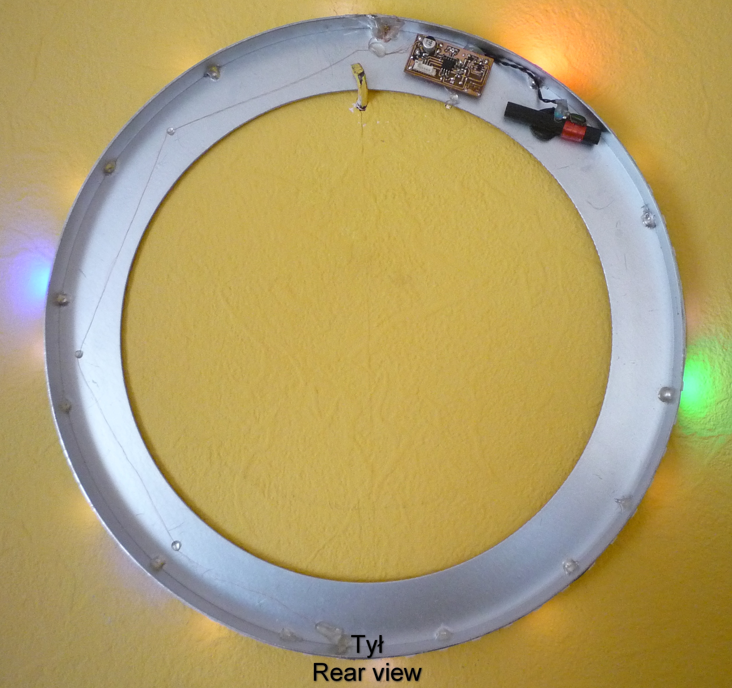
Finally I took a 2-layer PCB 40 by 20 mm (1.6 by 0.8 inch) and etched one layer (top). The bottom layer was not etched; it acts as a ground plane to enhance the immunity to external fields. I used several vias to connect top and bottom layer together. All components but DCF receiving module and X-tal were assembled on the top layer. The PCB and the ferrite antenna are mounted on the back of the clock using hot glue.
I use a tiny AC/DC Adapter with the USB-A socket to supply the clock. The connection between the adapter and the clock is made using thin magnet wire. The reason? The cable should be invisible to the eyes of my wife (otherwise the clock has to go to the garage instead it can stay at home).
4. Software
I wrote the code in C and compiled it with AVR Studio 4.19. The software uses about 5 kB of the program memory and about 200 B of data memory.
The software structure is as follows – every 20 milliseconds I get an interrupt from a timer. In the interrupt routine: (i) I decode DCF signal, (ii) I acquire a photodiode signal, (iii) I calculate the actual time and (iv) I display the time on the LED strip. After the interrupt is served, the microcontroller goes to the main loop and sleeps in idle mode for the next ~15 milliseconds. A watchdog with time interval of 32 ms guarantees fast recovery after the malfunction.
For the decoding of the DCF signals I used several mechanisms to assure the decoded time is correct. My motivation was “better not to display time than to display a wrong time”. Therefore, although I display only hours, minutes and seconds I also acquire months, years etc. For all data I run plausibility checks, e.g. is the month number between 1 and 12? Moreover, I examine all parity bits, start bits, time start bits. Finally, always two subsequent minutes are checked and compared to each other. Only if all tests are passed, the time is adjusted. To validate received bits I used the webpage (link) that presents the decoded bits live. Additionally, huge archive of the DCF signal is available.
Because of the interference of the DCF module by the strip I implemented following functionality. If during last 12 hours no correct DCF signal has been decoded, then at 3 a.m. the strip is switched off. As soon as correct time signal is received, the supply of the strip is recalled. I decided to do this at 3 a.m., since at that time one always has a correct CET/CEST time no matter which day of the year. On the other hand it is OK to switch the clock at 3 a.m. for 2-3 minutes, since at that time nobody at home reads out the time, anyway.
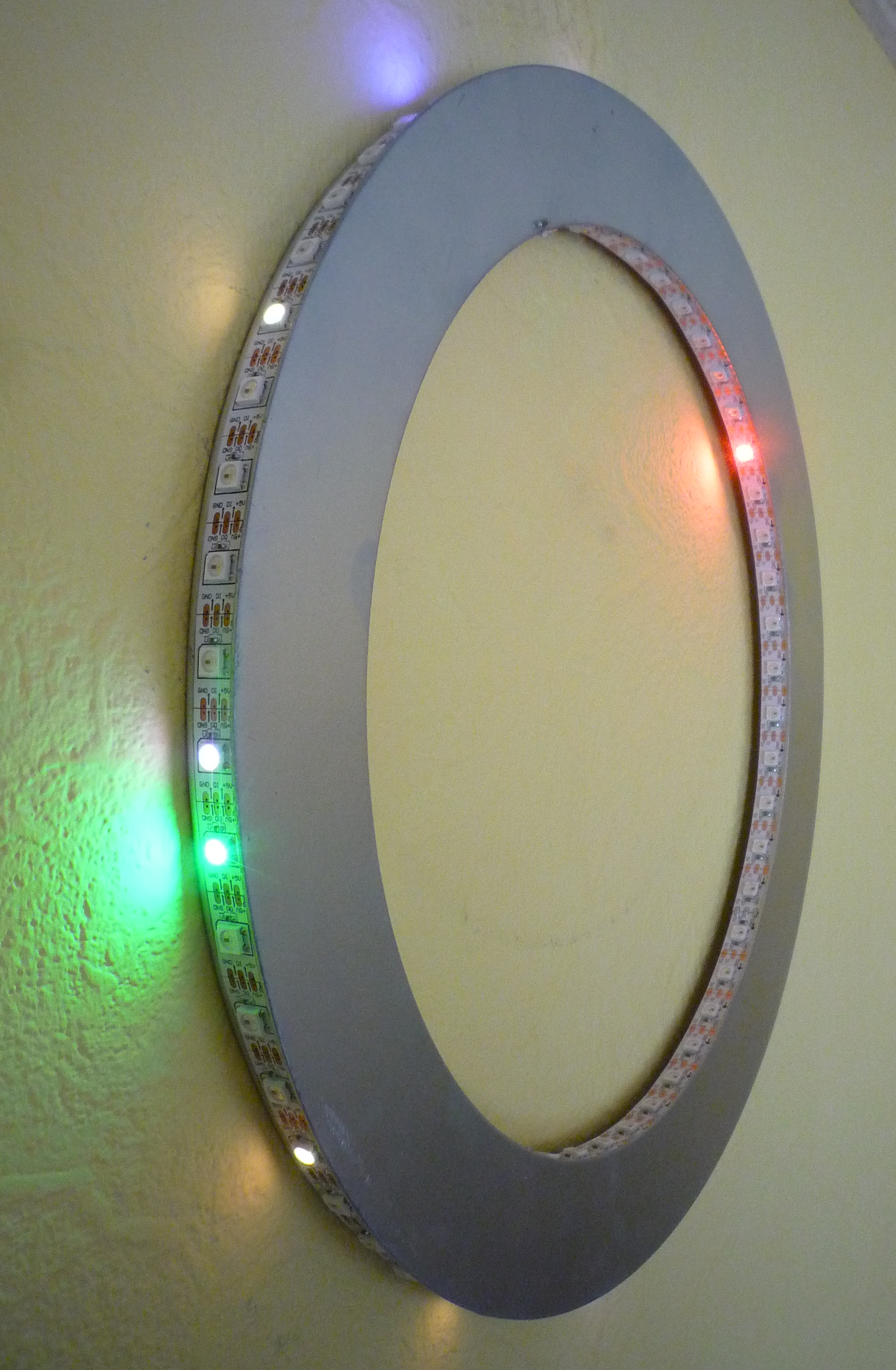
To control the WS2812B strip I used „light weight WS2812 lib”, and added a gamma correction. Additionally, to meet the brightness adjustment requirement I correlated ADC brightness values with the brightness set to the LED strip. For this I took reference measurements at different light levels, put them in the sheet, performed exponential fitting and finally I generated a transform table with coefficients.
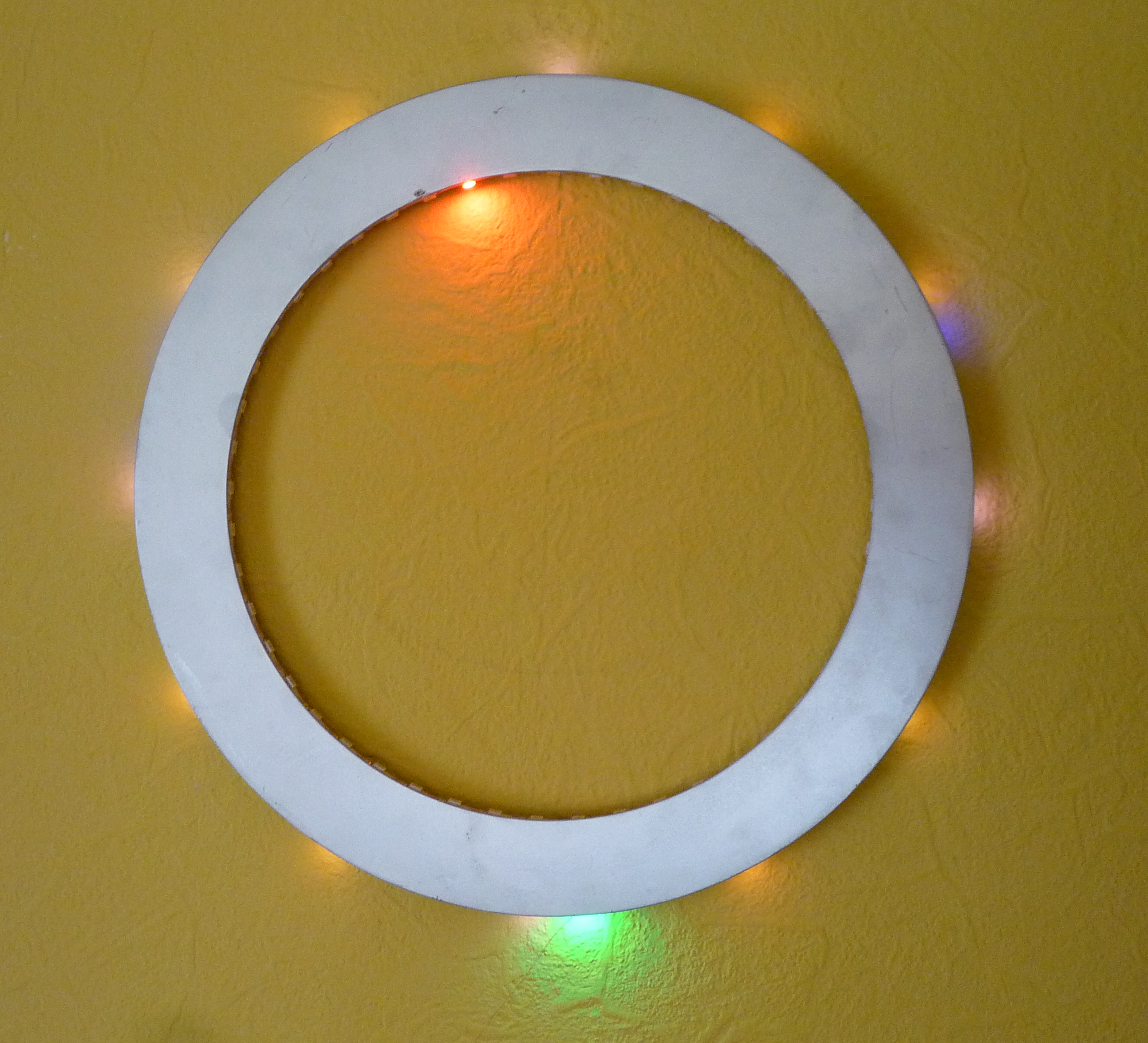
5. Housing
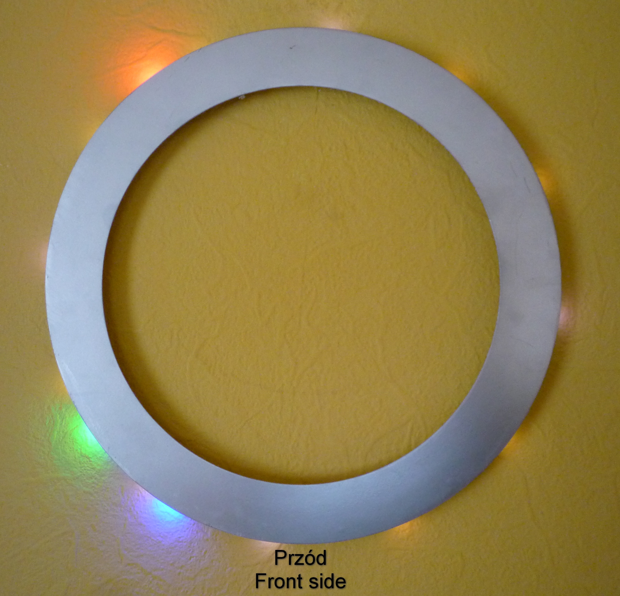
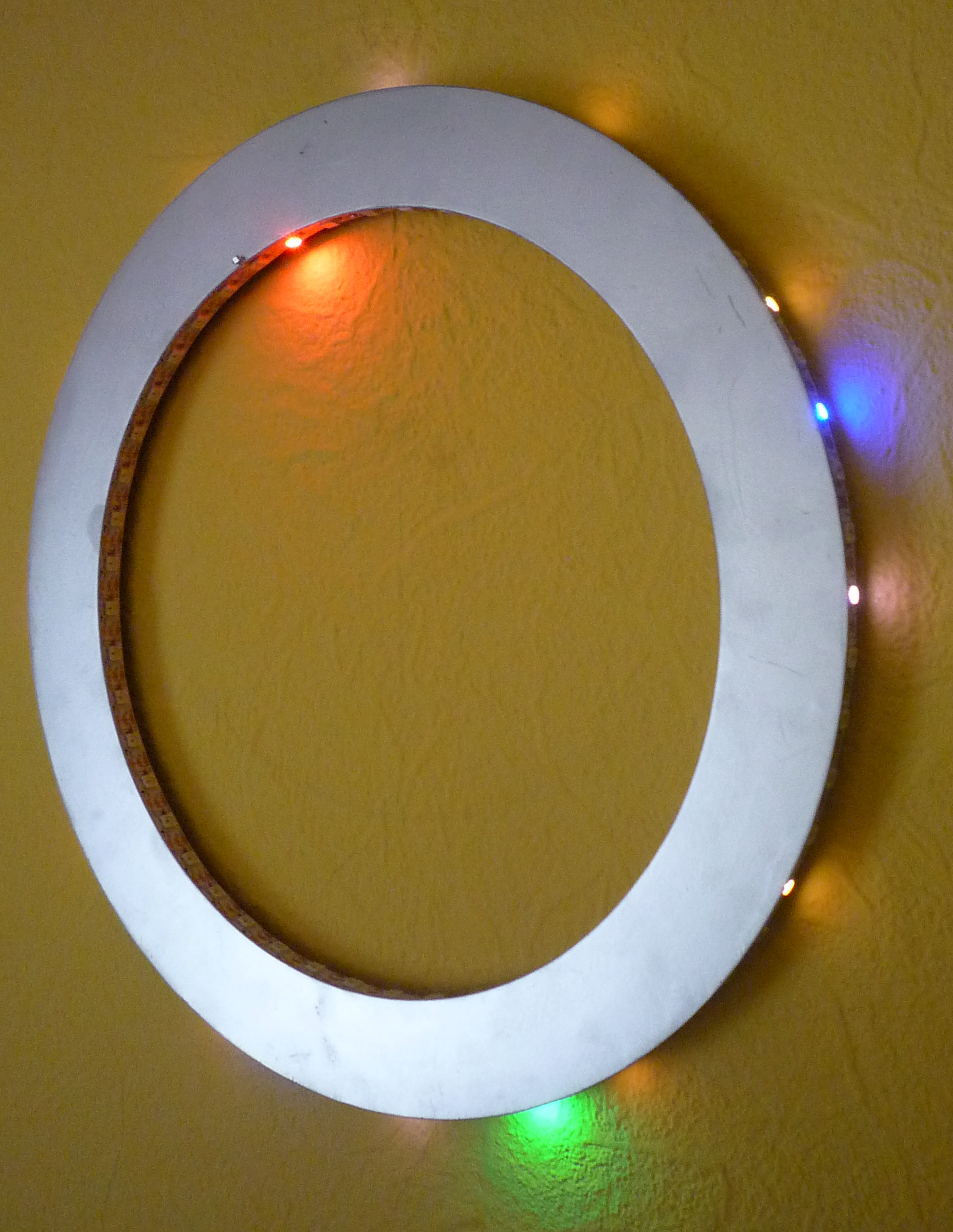
Also here a minimalistic idea – use only as much as you need. The housing consists of two metal pieces – a metal strip of diameter 32 cm (12.6 inch), 1.5 cm (0.6 inch) wide. Second one is a ring that mainly covers the PCB and the antenna. Both steel parts are welded together. Eventually I painted the clock using silver spray paint.
6. Time readout
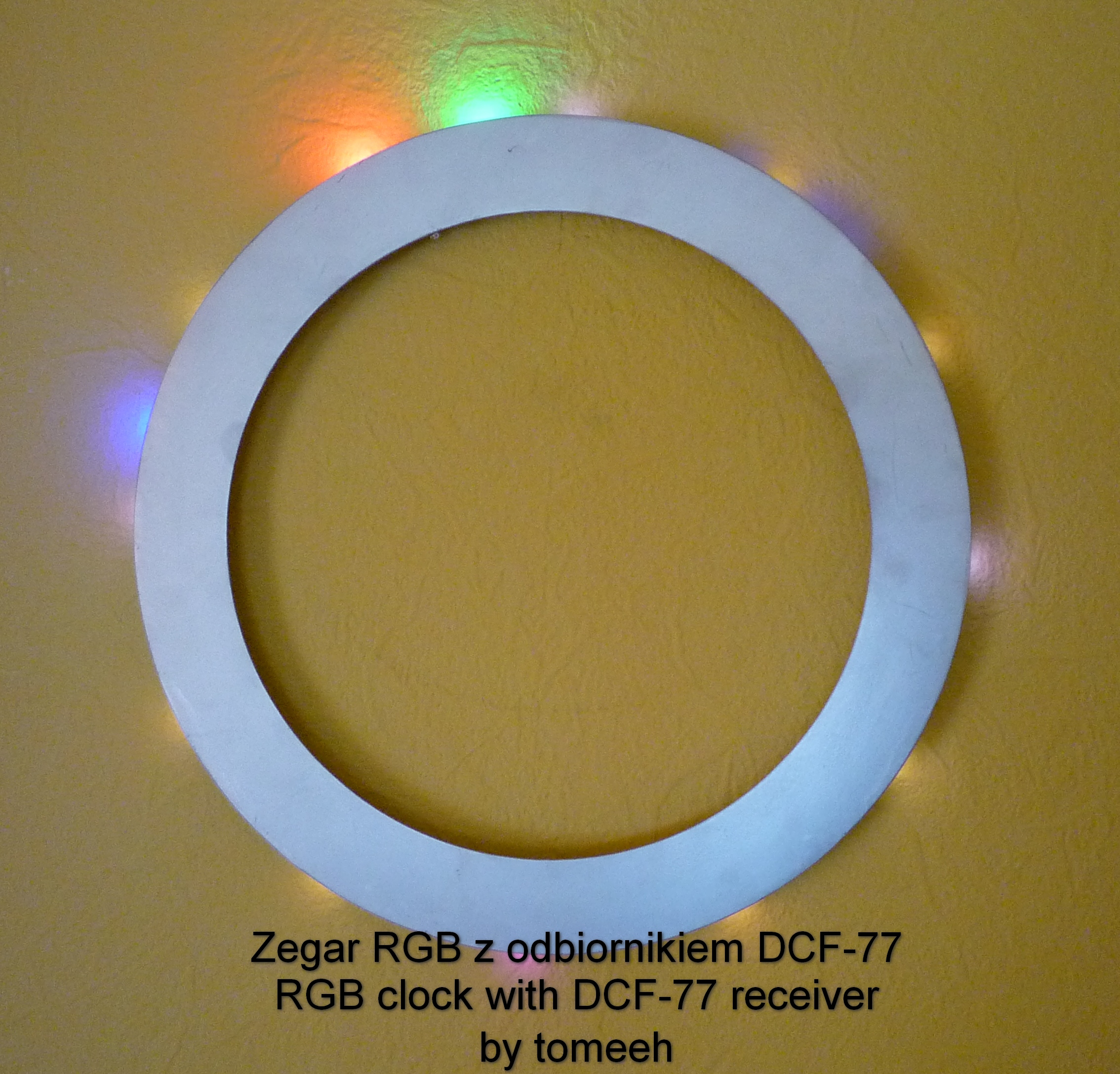
Three colors RGB correspond to the clock hands as follows: hour hand – red, minute hand – green, seconds’ hand – blue. In order to make the readout easier I display markings: white at 12, 3, 6, 9 and yellow at other hours. Additionally the marker from 6 o’clock is pink if the DCF synchronization within current hour was successful. To insert some gimmicks, I added some rotary effects that appear in case any hand changes its position.
To show that the strip is functioning directly after applying the power to it, there is a demo mode “falling ball”. After that the display goes off and the DCF signal is analyzed prior time synchronization.
Check the photos and the video.