Continue to Site

Welcome to EDAboard.com

Welcome to our site! EDAboard.com is an international Electronics Discussion Forum focused on EDA software, circuits, schematics, books, theory, papers, asic, pld, 8051, DSP, Network, RF, Analog Design, PCB, Service Manuals... and a whole lot more! To participate you need to register. Registration is free. Click here to register now.

[SOLVED] How to design specific filter ?

Status
Not open for further replies.

Ibtissam Aziz

Newbie level 4
Joined
Jan 17, 2015
Messages
6
Helped
0
Reputation
0
Reaction score
0
Trophy points
1
Activity points
61
Hello,

I studied filter design, I know usual canonical forms to express 1st and 2nd order filter.
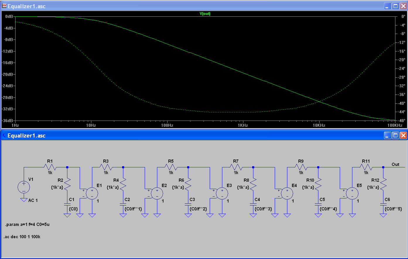
These forms lead us to -20/-40dB per decade. I was wondering how to design filters that aren't -20/-40..etc dB/dec.
Is there other mathematical tools to do it ? I found schematics and tryed to compute transfert function and I couldn't make the identification to canonical form.

Thanks for any help :smile:
 

One RC gives a filter that is 20dB per decade, two separated RCs give 40dB per decade, three separated RCs give 60dB per decade etc. That is how RC filters work.
You can make filters that have sharper cutoffs but they have some ripple in the passband and the maximum attenuation might not be much.
 

You can make filters that have sharper cutoffs .....
Yes - but only in the vicinity of the pole frequency. In the other frequency regions the slope always approaches n*20 dB/dec.
 

In case you want to customize a rolloff curve so it is shallower....
You can tap at different positions on the resistor in an RC filter. That is, using a potentiometer.


Filter action starts at the same frequency (159 Hz). It is most pronounced in the lefthand network. Output approaches zero at higher frequencies.

Filter action is less sharp in the other networks. They mix some input with some output. Output does not approach zero at higher frequencies.
 

Yes - but only in the vicinity of the pole frequency. In the other frequency regions the slope always approaches n*20 dB/dec.

(Sorry this BB has taken the policy decision to delete the context of your point, but) you're not always correct.

In the late 70s I built commutating capacitor N-path bandpass filter, centre frequency ~4khZ. Q ~4000. With 10% capacitors and resistors. The rolloff would have been 20dB in 10Hz, i.e. considerably more than 20dB/decade :)

And then there are crystal filters, of course. And SAW filters, some with extremely curious phase/frequency responses, e.g. for chirped radars :)
 

Why would you want to?
That is only of interest in an academic sense.
I see no reason to do it in practice.

For example I'd like to produce pink noise from white noise and I need to make a -10dB/dec filter. I found schematics which can realise this function but I wanted to know how to design it since every filter i know is -n*20dB/dec with n >=1.
 

A pink noise filter isn't a simple low-pass. The 10 dB/decade frequency response can be only implemented as a combination of poles and zeros, e.g. as a RC ladder circuit. See e.g. **broken link removed**

The design method is an approximation.
 

A pink noise filter isn't a simple low-pass. The 10 dB/decade frequency response can be only implemented as a combination of poles and zeros, e.g. as a RC ladder circuit. See e.g. **broken link removed**

The design method is an approximation.

Yes i saw this article during my research, but how do you approximate a given curve with analog design ?
I tried to compute the transfert function of this filter. But I can't formulate it to get a known form.
So it must be some other mathematical tools to do it.
 

I don't understand what you mean with "known form"? It's a passive RC network, it's transfer function can be derived by applying basic AC network calculation. In this case, only the magnitude matters.

Then use a nonlinear solver to fit the transfer curve to the intended magnitude characteristic. You can e.g. use the Excel solver or the MINPACK library. A convenient tool is also the PSpice optimizer.
 

I mean once you compute tranfer function you can identify elements from the canonic forms
**broken link removed**
It is in french but you will get it.
I can bode plot by hand if get one of these function.
For example if I get :

HTML:
 [/COLOR]
        R1
       ___      
in --+|___|-----+ out
             |            .-.
            | |
            | |R2
            '-'
             |     
            --- C1
            ---
             |
--------+-----+
I found function transfert is (1+jR2C1w)/(1+j(R1C1+R2C2)w)

And I can't make the link between 1st order low pass form (1/(1+jTow))
 

I found function transfert is (1+jR2C1w)/(1+j(R1C1+R2C2)w)

And I can't make the link between 1st order low pass form (1/(1+jTow))
The transfer function is a pole-zero-pair, in this case acting as lag-lead element. It can't be mapped to a pure low-pass (pole).

The pole-zero pair K*(1+Td s)/(1+T1 s) should be admitted as another canonical form in your table, it's a basic building block for frequency equalizers with arbitrary characteristic like your pink noise filter. It's also designated PDT1 in control theory literature.

The form is similar to the all-pass listed in your table, but the latter is behaving different due to the RHP zero.
 
a pink noise filter uses -3dB/oct VS -6dB/oct

You may be interested in the Nth order LC filters where you can design passband ripple or linear phase or max. flat and skirt band reject levels such as Butterworth , Causer, Gaussian etc.

you can also find chips that do 5th order filters with variables,... switched cap, and other implementations where you can choose the parameters.
 

Well thank you you taught me something :) (I'd like to read more about this kind of filter, do you have any link,book,.. for me ?)
So, if I cascade several of these specific filters and place correctly poles and zeros I should be able to get what I want -10dB/dec for example.
Am I right ?
And to do that I'll need to use some solver to aproximate the curve I want to follow to determine the values of the components.
 

Unfortunately I don't have specific literature. See below an example of a 5-stage equalizer using buffer isolated lag-lead-circuits. The time constants are simply chosen as a geometrical series. You can further improve the response by individualy tuning the values.


I also appended the LTSpice file. The buffer isolated implementation is more easy to calculate than the RC ladder circuit in your example, but the behaviour is similar.
 

Attachments

  • Equalizer1.zip
    1.1 KB · Views: 71

So, if I cascade several of these specific filters and place correctly poles and zeros I should be able to get what I want -10dB/dec for example.


Solutions are easy to find if you know the name and know whereto look.. Example.

-10dB/dec = Pink Noise Filter
 

sunnyskyguy:

Indeed, in the late 70s I built a pink noise generator using some of the schematics you show in your link.
The MM5937 white noise generator was a wonderful little IC, although its sequence was not very long would repeat every two or three seconds. One could listen to a "bump" when this happened.
 

Status
Not open for further replies.

Similar threads

Part and Inventory Search

Welcome to EDABoard.com

Sponsor

Back
Top