Karthikeyan.K
Newbie level 4
Hai all.
Please anybody help me on this.
I'm using C8051F120 micro controller. In data sheet, they said that any GPIO Pin can be configured as either PUSH-PULL output or Open Drain Output.
I initially doesn't know about what PUSH-PULL and Open drain are?
In this forum I found the following explanation regarding this. Please refer this before my question.
open drain push pull
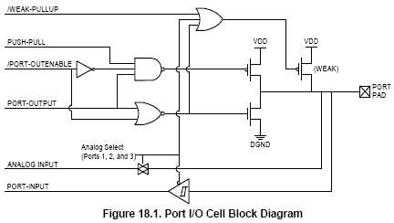
The push-pull output actually uses two transistors. Each will be on to drive the output to the appropriate level: the top transistor will be on when the output has to be driven high and the bottom transistor will turn on when the output has to go low.
The open-drain output lacks the top transistor. When the output has to go high you simply turn off the bottom transistor, but the line is now pulled high only by the pullup resistor.
Your micro allows you to select between the two types, which means that by setting some bits in some register you actually enable/ disable the top transistor and enable/disable the pullup (if internal, otherwise you just disable the top transistor and have to use an external pullup)
The advantage of the push-pull output is the higher speed, because the line is driven both ways. With the pullup the line can only rise as fast as the RC time constant allows. The R is the pullup, the C is the parasitic capacitance, including the pin capacitance and the board capacitance.
The push-pull can typically source more current. With the open-drain the current is limited by the R and R cannot be made very small, because the lower transistor has to sink that current when the output is low; that means higher power consumption.
However, the open-drain allows you to cshort several outputs together, with a common pullup. This is called an wired-OR connection. Now you can drive the output low with any of the IO pins. To drive it high all ouputs have to be high. This is advantageous in some situations, because it eliminates the external gates that would otherwise be required.

So now my question.
According to the explanation (or according my understanding), PUSH-PULL, Open Drain both configurations are for making a GPIO pin as output only?
If so, How can I make the GPIO Pin as Input?
Or else which configuration is suited for Input Pin?
Please explain me anybody? Thanks in advance.
Please anybody help me on this.
I'm using C8051F120 micro controller. In data sheet, they said that any GPIO Pin can be configured as either PUSH-PULL output or Open Drain Output.
I initially doesn't know about what PUSH-PULL and Open drain are?
In this forum I found the following explanation regarding this. Please refer this before my question.
open drain push pull
The push-pull output actually uses two transistors. Each will be on to drive the output to the appropriate level: the top transistor will be on when the output has to be driven high and the bottom transistor will turn on when the output has to go low.
The open-drain output lacks the top transistor. When the output has to go high you simply turn off the bottom transistor, but the line is now pulled high only by the pullup resistor.
Your micro allows you to select between the two types, which means that by setting some bits in some register you actually enable/ disable the top transistor and enable/disable the pullup (if internal, otherwise you just disable the top transistor and have to use an external pullup)
The advantage of the push-pull output is the higher speed, because the line is driven both ways. With the pullup the line can only rise as fast as the RC time constant allows. The R is the pullup, the C is the parasitic capacitance, including the pin capacitance and the board capacitance.
The push-pull can typically source more current. With the open-drain the current is limited by the R and R cannot be made very small, because the lower transistor has to sink that current when the output is low; that means higher power consumption.
However, the open-drain allows you to cshort several outputs together, with a common pullup. This is called an wired-OR connection. Now you can drive the output low with any of the IO pins. To drive it high all ouputs have to be high. This is advantageous in some situations, because it eliminates the external gates that would otherwise be required.
So now my question.
According to the explanation (or according my understanding), PUSH-PULL, Open Drain both configurations are for making a GPIO pin as output only?
If so, How can I make the GPIO Pin as Input?
Or else which configuration is suited for Input Pin?
Please explain me anybody? Thanks in advance.