Continue to Site

Welcome to EDAboard.com

Welcome to our site! EDAboard.com is an international Electronics Discussion Forum focused on EDA software, circuits, schematics, books, theory, papers, asic, pld, 8051, DSP, Network, RF, Analog Design, PCB, Service Manuals... and a whole lot more! To participate you need to register. Registration is free. Click here to register now.

wireless ( 433Mhz ) communication between PIC16F72 and raspberry pi

Status
Not open for further replies.

boiler95

Member level 1
Joined
Jan 7, 2011
Messages
38
Helped
1
Reputation
2
Reaction score
1
Trophy points
1,288
Activity points
1,731
Hi Guys,

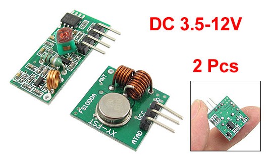
I'm trying to transfer data between PIC16F72 and raspberry pi (Model B, Rev2) using a cheap 433Mhz module from Ebay.


I'm planning to DIY a weather station and wireless is an essential part of it. The communication is one way from PIC to RPI and i have soldered a 17.3 cm wire as an antenna.

data needs to be transmitted probably for 12 meters max.

i'm using Manchester encoding here. PIC acts a s transmitter and RPI acts a receiver.

however the problem is i'm unable to transmit successfully anything.

i have the folowg transmitted from PIC16F72

4 Bytes preamble 0xAAAAAAAA
2 Bytes start of data 0xAB38
20 bytes of data (This is just AAAA.... , in future it will be replaces by data from all the sensors.)
1 byte of Check sum.

The problem i believe, is in the receiver part. the bloody data that i get is always corrupted no mater what !!!!!

i have tried sending 2000bps 2250bps .. (and much lower as well but in vain)

sometimes Preamble, start of data is detected but data is corrupted. but this happens at random sometimes nothing is detected. I'm been looking into it for days now without progress :bang:

i have posted the entire code for reference. Code for raspberry PI used the wringPI Api and is in C .. That of PIC is written in ASM for better control over timing.

i'm using pin 13 (wringPi pin 2) on RPI for reception.
the idea is to detect atleasst 3 bytes of preamble. and then the start of data and then the data itself.
i haven't checked the checksum part yet, as i'm printing the data received and checking it manually.

on the PIC side, i'm using RB5 as an o/p port connected to the TX.
Timer 1 is used to precisely to construct ( send) the required waveform with the correct timing i have tried sending 400us , 600us and 200us pulses with 400us being much better in the sense that the receiver is at least able to detect corrupt data.
i'm using RC4 as a led o/p. and Rb0 for external interrupt to start the transmission.

Any help is appreciated.

Thanks,
VirtualVat


Code C - [expand]
1
2
3
4
5
6
7
8
9
10
11
12
13
14
15
16
17
18
19
20
21
22
23
24
25
26
27
28
29
30
31
32
33
34
35
36
37
38
39
40
41
42
43
44
45
46
47
48
49
50
51
52
53
54
55
56
57
58
59
60
61
62
63
64
65
66
67
68
69
70
71
72
73
74
75
76
77
78
79
80
81
82
83
84
85
86
87
88
89
90
91
92
93
94
95
96
97
98
99
100
101
102
103
104
105
106
107
108
109
110
111
112
113
114
115
116
117
118
119
120
121
122
123
124
125
126
127
128
129
130
131
132
133
134
135
136
137
138
139
140
141
142
143
144
145
146
147
148
149
150
151
152
153
154
155
156
157
158
159
160
161
162
163
164
165
166
167
168
169
170
171
172
173
174
175
176
177
178
179
180
181
182
183
184
185
186
187
188
189
190
191
192
193
194
195
196
197
198
199
200
201
202
203
204
205
206
207
208
209
210
211
212
213
214
215
216
217
218
219
220
221
222
223
224
225
226
227
228
229
230
231
232
233
234
235
236
237
238
239
240
241
242
243
244
245
246
247
248
249
250
251
252
253
254
255
256
257
258
259
260
261
262
263
264
265
266
267
268
269
270
271
272
273
274
275
276
277
278
279
280
281
282
283
284
285
286
287
288
289
290
291
292
293
294
295
296
297
298
299
300
301
302
303
304
305
306
307
308
309
310
311
312
313
314
315
316
317
318
319
320
321
322
323
324
325
326
327
328
329
330
331
332
333
334
335
336
337
338
339
340
341
342
343
344
345
346
347
348
349
350
351
352
353
354
355
356
357
358
359
360
361
362
363
364
365
366
367
368
369
370
371
372
373
374
375
376
377
378
379
380
381
382
383
384
385
386
387
388
389
390
391
392
393
394
395
396
397
398
399
400
401
402
403
404
405
406
407
408
409
410
411
412
413
414
415
416
417
418
419
420
421
422
423
424
425
426
427
428
429
430
431
432
433
434
435
436
437
438
439
440
441
442
443
444
445
446
447
448
449
/*****************************
* Pin 13 ( physical) or Pin 2 in wiringPi is used
* Preamble of 2 bytes or 16 bits is sent first.
* Check sum is yet to be decided.
* bit rate of 2.5Khz will be considerded. This means 400us per bit
******************************/
#include <stdio.h>
#include <stdlib.h>
#include <wiringPi.h>
#include <signal.h>
#include <time.h>
#include <stdint.h>
#include <pthread.h>
#include <math.h>
#include <string.h>
 
#define PULSEWIDTH  600000  // in nano seconds
#define TOLERANCE   100000   // in nano seconds
#define MIN_PREAMBLE_BITS 24        // This is the minimum bits in the preamble that needs to be detected.
 
#define RXPIN 2     // This is pint 13 on physical layout
#define ACTIVETIME 90   // timer befor main thread exit, we need to re think this strategy
#define DATABYTES   21  // 20 bytes of data or 160 bits. (overall 3 bytes preamble so 178 bits or 71.2 ms burst )
#define PRIORITY 99
int result[DATABYTES * 8] ;
int start_of_data[8] = {0,0,1,1,1,0,0,0};
 
typedef int bool ;
#define true 1
#define false 0
 
// synchronization related.
typedef int syncState ;
#define notSynced 0
#define synching 1
#define synched 2
 
typedef int processState ;
#define PRESYNC 0
#define POSTSYNC 2
#define DATA 3
 
// Timer related
#define CLOCKID CLOCK_REALTIME
#define SIG SIGRTMIN
#define TIMERVAL 60000000000    // this is the timer value in ns, this is 1 min
 
// global variables
timer_t syncTimer;      // this is the timer used in sync timing
struct itimerspec its;  // used in the creation of timer ( timer spec )
struct sigevent sev;    // used in timer creation
 
uint64_t count1 ;           // used to calculate diff
uint64_t count2 ;
 
// forward declarations
void initialize(void);
long getTimeElapsed(time_t);
uint64_t getCountDiff(void);
void resetOnError(void);
void initializeTimer(void);
 
#define errExit(msg)    do { perror(msg); exit(EXIT_FAILURE); \
                         } while (0)
 
 
processState procState ;
syncState synchState;
int currentBit;
int prevBit ;
int iter ;
int const pulseWidthMax = PULSEWIDTH + TOLERANCE ;
int const pulseWidthMin = PULSEWIDTH - TOLERANCE ;
int const pulseHalfWidthMax = (PULSEWIDTH / 2 ) + TOLERANCE ;
int const pulseHalfWidthMin = (PULSEWIDTH / 2 ) - TOLERANCE ;
 
bool allDataRecieved = false  ;
 
pthread_mutex_t var ;
 
 
void storeDecimalToHex(uint8_t decimalValue, char* hexResult)
{
    static int i = 0 ;  // static because we call it repeatedly
    int rem ;
    int iter = 1 ;
    while(decimalValue != 0)
    {
        rem = decimalValue%16 ;
    switch(rem)
    {
        case 10:
            hexResult[i+iter]='A';
            break;
        case 11:
            hexResult[i+iter]='B';
            break;
        case 12:
            hexResult[i+iter]='C';
            break;
        case 13:
            hexResult[i+iter]='D';
            break;
        case 14:
            hexResult[i+iter]='E';
            break;
        case 15:
            hexResult[i+iter]='F';
            break;
        default:
            hexResult[i+iter]=rem+'0';
            break;
    }
 
    i++ ;   // static so that we can track the number of bits done.
    iter = -1 ; // this is local
    decimalValue=decimalValue/16 ;
    }
 
    if(i == ((DATABYTES - 1 ) * 8 ) - 1 ) // if this is the last bit. then
    {
        hexResult[i+1] = '\0'; // add the end of string so that we can print it.
    }
}
 
 
int getCheckSum(int* result)
{
    int bitcount = 0 ;
    uint8_t calculatedChecksum = 0 ; // use 8 bit integer so that it will overflow after 255
    int index = 7 ;
    while(bitcount < ((DATABYTES - 1) * 8)) // only 19 bytes is data last byte is checksum
    {
        calculatedChecksum = calculatedChecksum + (*(result + bitcount )) * ((uint8_t)pow(2 , index)); // &(result + bitcount ) will point to a bit in each iteration. index starts from 7 ends to 0 then wraps to 7.
        if(index == 0)
        {
            index = 7 ; // this means one byte is over , reset the index to 7
        }
        else
        {
            index -- ; // decrement the index during each iteration so that the bits are multiplied by appropriate powers of 2.
        }
 
        bitcount++ ; // increment during each iteration to keep track of number of bits
    }
 
    // Xor the resulting value with 255 (0xFF)
    calculatedChecksum = calculatedChecksum ^(uint8_t)255 ;
 
    // Add 1 to the result
    calculatedChecksum = calculatedChecksum + (uint8_t)1 ;
 
    return calculatedChecksum ;
}
 
void checkAndPrintData()
{
    // we need to first get the check sum.
    // The transmitter transmits MSB first , so the first memory location contains the MSB.
    // Check sum is the last byte.
 
    // -------------- extract check sum -------------------------------
    int i = 0 ;
    unsigned int extractedCheckSum = 0 ;
    while(i < 8)
    {
        extractedCheckSum = extractedCheckSum + ((*(result + (DATABYTES * 8) - 1  - i )) * ((uint8_t)pow(2 , i))) ;
        i++ ;
    }
 
    // -------- calclate checksum from the receieved data ------------------------;
    unsigned int calculatedCheckSum = 0 ;
    calculatedCheckSum = getCheckSum(result);
    if(calculatedCheckSum != extractedCheckSum )
    {
        printf("Check sum do not match error in transmission \n");
    }
    else
    {
        printf("Calculated checksum is %d , checksum receieved in the packet is %d \n ", calculatedCheckSum , extractedCheckSum);
    }
 
    // ----------------------- Print data --------------------------.
    char hex[39] ; // This is where data is stored. we have 19 bytes of data each bytes takes 2 hex number to represent. so 19 x 8 = 38 + 1 (end of string '\0' ) = 39 is array size needed.
    int bitcount = 0 ;
    uint8_t byteValDecimal = 0 ; // this is used to keep track of every byte in decimal ;
    int index = 7 ;
    while(bitcount < (DATABYTES - 1) * 8 ) // DATABYTES -1 because 20th byte is checksum and not data
    {
        // first get the byte value in decimal.
        byteValDecimal = byteValDecimal + (*(result + bitcount )) * (uint8_t)pow(2 , index);
        if(index == 0)
        {
            index = 7 ; // At this point 1 byte is over. convert this value to hex and store it.
            storeDecimalToHex( byteValDecimal, hex) ;
        }
        else
        {
            index-- ;
        }
 
        bitcount++ ; // increment during each iteration to keep track of number of bits
    }
 
    printf("Hexadecimal number: %s  \n",hex);
}
 
int main(void)
{
    if(wiringPiSetup() == -1 )
        errExit("Error initializing wiring pi");
    pinMode(RXPIN, INPUT);
    initialize();
    printf("main thread executing delay for %d sec \n", ACTIVETIME ) ;
    int i = ACTIVETIME;
    while(i > 0)
    {
            delay(1000 );
            // check meanwile if we have data.
            pthread_mutex_lock(&var);
            if(allDataRecieved == true )
            {
                //checkAndPrintData();
                int iterator = 0 ;
                while(iterator < (DATABYTES * 8))
                {
                    iterator++ ;
                    printf("%d", result[iterator]);
                    if(iterator % 8 == 0 )
                    {
                        printf("\n");
                    }
                }
                break ;
            }
            pthread_mutex_unlock(&var);
            i-- ;
 
        }
    printf("main thread finished delay for %d sec \n bye !!", ACTIVETIME ) ;
    exit(EXIT_SUCCESS);
 
}
 
void _ISROnAllEdges(void)
{
    currentBit = digitalRead (RXPIN) ;
    uint64_t diff = getCountDiff();
    if(procState == PRESYNC )
    {
        if(synchState == notSynced )
        {
             /* start   timer */
            if (timer_settime(syncTimer, 0, &its, NULL) == -1)
                errExit("timer_settime");
 
            /* mark the process as initializing */
            synchState = synching ;
 
            /* initialize count1 */
            count1 = TIMERVAL;
         }
         else if(synchState == synching )
         {
            if(diff > pulseWidthMin && diff < pulseWidthMax)
            {
                if(iter < MIN_PREAMBLE_BITS)
                {
                    if(currentBit == prevBit)
                    {
                     /*This is error*/
                        resetOnError();
                        return ;
                    }
                    else
                    {
                        prevBit = currentBit ;
                        iter++ ;
                    }
                }
                else if(iter >= MIN_PREAMBLE_BITS)
                {
                    /* if we are here then we have got atleast 1010
                    There can be more 10101.. or we can get the 00111000 that preceeds the data.
                    We need to identify the start of 00111000 before moving to the next step*/
                    if(currentBit == prevBit)
                    {
                        if(currentBit == 1)
                        {
                           printf("Preamble detected \n ");
                           synchState = synched ;
                           procState =  POSTSYNC ;
                           iter = 0 ;
                        }
                        else
                        {
                        /* Current bit and previous bit are 0 , this is not possible in preamble so error*/
                            resetOnError();
                        }
                    }
                    else
                    {
                        /*Still we are in preamble detection */
                        prevBit = currentBit ;
                        iter++ ;
                    }
                }
                count1 = count2 ; //Advance to next bit
            }
            else if(diff > pulseHalfWidthMin && diff < pulseHalfWidthMax )
            {
                return ; // wait for the next edge.
            }
            else
            {
                /* Error out of sync */
                resetOnError();
            }
         }
     }
     else if( procState == POSTSYNC )
     {
        printf("In post sync \n");
        if(diff > pulseWidthMin && diff < pulseWidthMax )
        {
            printf("In post sync: time matched \n");
            /* this is where we identify the string of 00111000 This is the start of data identifier */
            if(currentBit == start_of_data[iter++])
            {
                printf("In post sync: iter = %d \n", iter);
                if(iter == 8 ) // all 8 bits are identified. next is start of data
                {
                    printf("Ready to accept data \n");
                    procState = DATA ;
                    iter = 0 ;
                }
                count1 = count2 ; // Advance to next bit.
            }
            else
            {
                printf("In post sync : expecting %d but %d detected \n", start_of_data[iter - 1] , currentBit);
                /*Error case since we are expecting all 1's */
                resetOnError();
            }
        }
        else if(diff > pulseHalfWidthMin && diff < pulseHalfWidthMax )
        {
                        printf("In post sync : Returning for next edge \n");
                        return ; // wait for the next edge.
        }
        else
        {
            printf("In post sync : Timing error %ld \n", (long)diff);
            /* Error out of sync */
            resetOnError();
        }
     }
     else if(procState == DATA)
     {
        if(diff > pulseHalfWidthMin && diff < pulseHalfWidthMax )
        {
            return ; // wait for the next edge.
        }
        if(iter < (DATABYTES * 8) )
        {
            if(diff <  pulseWidthMin || diff >  pulseWidthMax)
            {
                printf("Timer problem %ld \n", (long)diff);
                result[iter++] = 2 ;
            }
            else
            {
                result[iter++] = currentBit ;
            }
        }
        else
        {
            // Done De-register the interrupt
            system ("/usr/local/bin/gpio edge 17 none") ;
            // update the global variable to indicate data is recieved.
            pthread_mutex_lock(&var);
                                            allDataRecieved = true ;
            pthread_mutex_unlock(&var);
            return ;
        }
        count1 = count2 ; // Advance to next bit
 
     }
}
 
void initialize(void)
{
    procState = PRESYNC ;
    synchState = notSynced;
    currentBit = 0 ;
    prevBit = 0 ;
    iter = 0 ;
 
    /*Elevate the thread priority*/
    if(piHiPri(PRIORITY) == -1)
        errExit("Unable to elevate thread priority, run program as root \n");
 
    initializeTimer() ;
    // instruct kernel to interrupt on all edges.
    wiringPiISR (RXPIN, INT_EDGE_BOTH ,  &_ISROnAllEdges) ;
}
 
 
void initializeTimer(void)
{
     /* Create the timer */
 
     sev.sigev_notify   = SIGEV_NONE;
     if (timer_create(CLOCKID, &sev, &syncTimer) == -1)
         errExit("timer_create");
 
     printf("timer ID   is 0x%lx\n", (long) syncTimer);
 
     /* Start   the timer later just fill the spec*/
 
     its.it_value.tv_sec = TIMERVAL /   1000000000;
     its.it_value.tv_nsec   = TIMERVAL % 1000000000;
     its.it_interval.tv_sec =   its.it_value.tv_sec;
     its.it_interval.tv_nsec = its.it_value.tv_nsec;
}
 
uint64_t getCountDiff(void)
{
    uint64_t nanosec = 0 ;
    struct itimerspec time_spec ;
    if(timer_gettime(syncTimer, &time_spec ) == -1)
            errExit("timer_getoverrun");
 
    count2 =  ((uint64_t)time_spec.it_value.tv_sec * (uint64_t)1000000000 ) + (uint64_t)time_spec.it_value.tv_nsec ;
    nanosec = count1 - count2 ;
    return nanosec ;
}
 
void resetOnError(void)
{
    /*This is error*/
    synchState = notSynced ; // error start all over.
    procState = PRESYNC ;
    iter = 0 ;
    prevBit = 0 ; // This forces the algorithm to proceed only when the pulses are 1
    currentBit = 0 ;
    /* if(timer_delete(syncTimer) == -1) // Timer is deleted an recreated in a new cycle
        errExit("Delete the timer");  No need of this because thn new time is set timer is automatically rearmed */
}


This is the transmitter code. (PIC)


Code ASM - [expand]
1
2
3
4
5
6
7
8
9
10
11
12
13
14
15
16
17
18
19
20
21
22
23
24
25
26
27
28
29
30
31
32
33
34
35
36
37
38
39
40
41
42
43
44
45
46
47
48
49
50
51
52
53
54
55
56
57
58
59
60
61
62
63
64
65
66
67
68
69
70
71
72
73
74
75
76
77
78
79
80
81
82
83
84
85
86
87
88
89
90
91
92
93
94
95
96
97
98
99
100
101
102
103
104
105
106
107
108
109
110
111
112
113
114
115
116
117
118
119
120
121
122
123
124
125
126
127
128
129
130
131
132
133
134
135
136
137
138
139
140
141
142
143
144
145
146
147
148
149
150
151
152
153
154
155
156
157
158
159
160
161
162
163
164
165
166
167
168
169
170
171
172
173
174
175
176
177
178
179
180
181
182
183
184
185
186
187
188
189
190
191
192
193
194
195
196
197
198
199
200
201
202
203
204
205
206
207
208
209
210
211
212
213
214
215
216
217
218
219
220
221
222
223
224
225
226
227
228
229
230
231
232
233
234
235
236
237
238
239
240
241
242
243
244
245
246
247
248
249
250
251
252
253
254
255
256
257
258
259
260
261
262
263
264
265
266
267
268
269
270
271
272
273
274
275
276
277
278
279
280
281
282
283
284
285
286
287
288
289
290
291
292
293
294
295
296
297
298
299
300
301
302
303
304
305
306
307
308
309
310
311
312
313
314
315
316
317
318
319
320
321
322
323
324
325
326
327
328
329
330
331
332
333
334
335
336
337
338
339
340
341
342
343
344
345
346
347
348
349
350
351
352
353
354
355
356
357
358
359
360
361
362
363
364
365
366
367
368
369
370
371
372
373
374
375
376
377
378
379
380
381
382
383
384
385
386
387
388
389
390
391
392
393
394
395
396
397
;**********************************************************************
;   This file is a basic code template for assembly code generation   *
;   on the PIC16F72. This file contains the basic code                *
;   building blocks to build upon.                                    *  
;                                                                     *
;   Refer to the MPASM User's Guide for additional information on     *
;   features of the assembler (Document DS33014).                     *
;                                                                     *
;   Refer to the respective PIC data sheet for additional             *
;   information on the instruction set.                               *
;                                                                     *
;**********************************************************************
;                                                                     *
;    Filename:      xxx.asm                                           *
;    Date:                                                            *
;    File Version:                                                    *
;                                                                     *
;    Author:                                                          *
;    Company:                                                         *
;                                                                     * 
;                                                                     *
;**********************************************************************
;                                                                     *
;    Files Required: P16F72.INC                                       *
;                                                                     *
;**********************************************************************
;                                                                     *
;    Notes: 20 bytes of data. 6 bytes of preamble. 1 start fo data byte . 1 byte Check sum *
;                                                                     *
;**********************************************************************
 
 
        list            p=16f72         ; list directive to define processor
        #include        <p16f72.inc>    ; processor specific variable definitions
        
        __CONFIG _CP_OFF & _WDTEN_OFF & _BODEN_OFF & _PWRTEN_ON & _HS_OSC
 
; '__CONFIG' directive is used to embed configuration data within .asm file.
; The lables following the directive are located in the respective .inc file.
; See respective data sheet for additional information on configuration word.


;***** VARIABLE DEFINITIONS
w_temp          EQU     0x20            ; variable used for context saving
w_temp1         EQU     0xA0            ; reserve bank1 equivalent of w_temp 
status_temp     EQU     0x21            ; variable used for context saving
ISDATA          EQU     0x40            ; ISDATA<1> is used to determine if the data is at edge of mid (Mid bit of bit edge), ISDATA<0> is used in calculation of Check Sum
TEMP            EQU     0x41
BITCOUNT        EQU     0x42    
CKS                     EQU     0x5E            ; This is the last bytes in the data block below. This is used to store the Check sum
 
        CBLOCK  0x43
        _DATA:28                                ; data is 20 bytes wide, 6 bytes of preamble, 1 byte start fo data followed by 1 byte of checksum total 28 bytes
        ENDC                                            ; End of Cblock , we can now access data by DATA , DATA+1 , DATA+2 etc..
 
 
        cblock
        DELAY
        DELAY_1
        DELAY_2
        endc


;**********************************************************************
        ORG     0x000             ; processor reset vector
 
        goto    main              ; go to beginning of program
 
 
        ORG     0x004             ; interrupt vector location
 
        movwf   w_temp            ; save off current W register contents (At this point 2 cycles are already over when interrupt is raised, use this in the count)
        movf    STATUS,w          ; move status register into W register
        bcf     STATUS,RP0        ; ensure file register bank set to 0
        movwf   status_temp       ; save off contents of STATUS register
 
                        
; isr code can go here or be located as a call subroutine elsewhere
                                BTFSC   INTCON, INTF            ; Check if this is and external interrupt routine
                                GOTO    EXT_INT_ROUTINE
                                BANKSEL PIR1
                                BTFSS   PIR1, TMR1IF
                                                GOTO    ISREND
; Handle timeout interrupt
; first check if it is bit edge.
                                                BTFSC   ISDATA, 1       ; if clear then it is bit edge.
                                                GOTO    MIDBIT          ; This interrupt is for mid bit
; Start of bit edge operations
                                                BTFSS   INDF, 7         ; bit edge. if 0 then tranamit 1 , if 1 then transmit 0
                                                GOTO    SEND_HIGH_EDGE_RELOAD ;  send a high and load the timer to interrupt in next 200uS (This is for bit edge )
; EBL : **** Start of edge bit low operations
                                                BANKSEL PORTB           ; This is 2 instruction cycle
                                                NOP
                                                NOP                                     ; These 2 NOP is to make the time taken since interrupt same for both EBL and EBH
                                                BCF             PORTB, RB5      ; send bit low and load count. (19)
                                                MOVLW   0x24            ; 0x31 for 400us , 0x3C for 600us
                                                MOVWF   TMR1L           ; 
                                                MOVLW   0xFE            ; 0xFC for 400us , 0xFA for 600us
                                                MOVWF   TMR1H           ;
                                                GOTO    BITEDGE_END     ;
; End of bit edge low operation
; EBH ***** Start of bit edge high operations
SEND_HIGH_EDGE_RELOAD   NOP
                                                BANKSEL PORTB
                                                BSF             PORTB, RB5      ; send bit High and load count. (19)
                                                MOVLW   0x24            ; 0x31 for 400us
                                                MOVWF   TMR1L           ; 
                                                MOVLW   0xFE            ; 0xFC for 400us
                                                MOVWF   TMR1H           ;
; End of bit edge high operations
BITEDGE_END                             BSF             ISDATA, 1       ; set it to indicate middle of the bit during next interrupt.
                                                GOTO    PREISR          ; Done goto PREISR so that we clear the interrupt.
; Start of mid bit operations
MIDBIT                                  BTFSS   INDF, 7         ; check MSB and transmit.
                                                GOTO    SEND_LOW_MID_RELOAD ;  send a low and load the timer to interrupt in next 200uS (This is for bit middle )
;MBH : ***** Start of mid bit high operations
                                                BANKSEL PORTB
                                                NOP                                     ; To adjust cycles
                                                NOP
                                                BSF             PORTB, RB5      ; 22 cycles till here.
                                                MOVLW   0x23            ; 0x30 for 400us , 0x3B for 600us
                                                MOVWF   TMR1L           ; 
                                                MOVLW   0xFE            ; 0xFC for 400us, 0xFA for 600us
                                                MOVWF   TMR1H           ;
                                                GOTO    BITMID_END      ;
; End of mid bit high operations
; MBL : ******  start of mid bit low operations
SEND_LOW_MID_RELOAD             NOP
                                                BANKSEL PORTB           ;
                                                BCF             PORTB, RB5      ; 22 cycles till here
                                                MOVLW   0x23            ; 0x30 for 400us 
                                                MOVWF   TMR1L           ; 
                                                MOVLW   0xFE            ; 0xFC for 400us
                                                MOVWF   TMR1H           ;
; end of mid bit low operations.
BITMID_END
                                                INCF    BITCOUNT                ; increment the bit count indicating we just transmitted a bit , This is used to determine end of transmission
                                                INCF    TEMP                    ; Increment the temp register, This is used to determine if a byte has been transmitted
                                                BCF             ISDATA, 1               ; Clear the flag to indicate next interrupt is for bit edge.
                                                RLF             INDF, F                 ; we just sent one bit now we need to shift once
                        
                                                MOVLW   0x08                    ; Check if 8 bits are transmitted.
                                                SUBWF   TEMP, W                 ; TEMP register is incremented every time a bit is transmitted so subract and see if result is 0
                                                BTFSS   STATUS, Z               ;
                                                GOTO    PREISR                  ; Zero bit is not set so 8 bits is not yet transmitted.
                                                CLRF    TEMP                    ; 8 bits (1byte) are done get ready for the next byte.
                                                INCF    FSR                             ; Increment FSR to point to next byte.
                        
                                                MOVLW   0xD8                    ; This corresponds to 184
                                                SUBWF   BITCOUNT, W             ; subtract the bit counts from this value , this tells us if we have transmitted all the bits.
                                                BTFSS   STATUS, Z                       
                                                GOTO    PREISR                  ; Zero bit not set, means we have still some bits to transmit.
 
                                                ; ************** At this point we are done transmitting the data *****************
                                                        BANKSEL T1CON
                                                        BCF             T1CON, TMR1ON   ; Stop the timer.
 
                                                        CALL    Delay                   ; 200us delay and lower the signal
 
                                                        BANKSEL PORTB
                                                        BCF             PORTB, RB5              ; lower the signal
 
                                                        BANKSEL PORTC
                                                        BSF             PORTC, RC4              ; Switch off the LED
 
                                                ; *************** End of transmission activity *********************************
 
PREISR                                  NOP
                                                BANKSEL PIR1
                                                BCF             PIR1, TMR1IF    ; clear the timer 1 interrupt flag so that we will get subsequent interrupts.
                                                GOTO    ISREND
; start of enternal interrupt routine handling.
EXT_INT_ROUTINE                 NOP                                             ; Because we can't label BANLSEL, This usually the start of the transmission, prestart kind off
                                                BANKSEL PORTB           
                                                ; initialize data to send
                                                CALL    INIT_DATA
                                                BCF             PORTB, RB5                      ; Clear RB5 , so we are sendin a low on signal.
                                                
                                                ; Calculate check sum to the 21st byte, this is actually 27th byte including preamble and data
                                                CALL    Cal_CKS
 
                                                MOVLW   0x43                            ; Point the FSR to the first location that we need to send.
                                                MOVWF   FSR
                                                
                                                BANKSEL PORTC
                                                BCF             PORTC, RC4                      ; Switch on LED indicating ready for transmission
 
                                                CALL    Delay_1s                        ; Interoduce a delay of 1 second
 
                                                BANKSEL TMR1L
                                                CLRF    TMR1L                   ; Start the timer from 00 (this is simoly done to give the receiever some more time to lock on.)
                                                CLRF    TMR1H
 
                                                BANKSEL T1CON
                                                BSF             T1CON, TMR1ON   ; Enable timer 1 interrupt.
 
                                                BCF             INTCON, INTF    ; Clear the external interrupt
; End of the enternal interrupt routine handling
ISREND                                  NOP
 
 
        bcf     STATUS,RP0        ; ensure file register bank set to 0
        movf    status_temp,w     ; retrieve copy of STATUS register
        movwf   STATUS            ; restore pre-isr STATUS register contents
        swapf   w_temp,f
        swapf   w_temp,w          ; restore pre-isr W register contents
        retfie                    ; return from interrupt


main
 
; Configure port b as output
                BANKSEL TRISB
                BCF             TRISB, RB5                      ; Configure RB5 as a output for data to be transmitted.
                BSF             TRISB, RB0                      ; Configure port B as input for external interrupt.
; Configure port c , RC4 as a LED output
                BANKSEL TRISC
                BCF             TRISC, RC4
                
                BANKSEL PORTC
                BSF             PORTC, RC4                      ; This will clear the LED
                CALL    Delay_1s
                BCF             PORTC, RC4                      ; This will on the LED
                CALL    Delay_1s
                BSF             PORTC, RC4                      ; This will clear the LED
                CALL    Delay_1s
                BCF             PORTC, RC4                      ; This will on the LED
                CALL    Delay_1s
                BSF             PORTC, RC4                      ; This will clear the LED
                CALL    Delay_1s
                
; Configure the timer 0
                BANKSEL T1CON
                CLRF    T1CON
                
 
; configure enternal interrupt
                BSF             OPTION_REG, INTEDG      ; interrupt on raising edge.
 
; Configure interrupt
                BANKSEL INTCON
                BSF             INTCON, GIE                     ; Enabel global interrupt. 
                BSF             INTCON, INTE            ; Enable external interrupt.
                BSF             INTCON, PEIE            ; enable pheripheral interript (This is for the timer 1 interrupt to fire)
                BANKSEL PIE1
                BSF             PIE1, TMR1IE            ; Enable timer 1 interrupt.
 
LOOP    NOP
                GOTO    LOOP
 
 
; Delay = 0.0002 seconds
; Clock frequency = 20 MHz
 
; Actual delay = 0.0002 seconds = 1000 cycles
; Error = 0 %
 
Delay
                        ;993 cycles
        movlw   0xC6
        movwf   DELAY
        movlw   0x01
        movwf   DELAY_1
Delay_0
        decfsz  DELAY, f
        goto    $+2
        decfsz  DELAY_1, f
        goto    Delay_0
 
                        ;3 cycles
        goto    $+1
        nop
 
                        ;4 cycles (including call)
        return
 
Cal_CKS
                        ; Addition of all data begin.
                                MOVLW   0x0C
                                MOVWF   TEMP                    ; Temp is iterated in every oteration, after 20 bytes are added(20 iterations) we will get 32 which is 100000 so we can check TEMP<5>
                                MOVLW   0x4A                    ;
                                MOVWF   FSR                             ; FSR is in all banks. And points to a location, in this case location is 0x46
                                MOVLW   0x00                    ;
ADD_ITER                BTFSC   TEMP, 5                 ;
                                GOTO    DONE_ADDING             ; We done adding all data bits
                                ADDWF   INDF, W                 ; Store result in W register
                                INCF    TEMP
                                INCF    FSR
                                GOTO    ADD_ITER
                        ; End of addition of data.
DONE_ADDING             CLRF    TEMP                    ; This is again used in interrupt
                                XORLW   0xFF                    ;
                                MOVWF   CKS
                                INCF    CKS                             ; Add 1 to the value, this finished the checksum.
                                RETURN
 
INIT_DATA
                        MOVLW   0xAA
                        MOVWF   _DATA                           ; Preamble starts
                        MOVWF   _DATA+1
                        MOVWF   _DATA+2
                        MOVWF   _DATA+3
                        MOVWF   _DATA+4                         ; Preamble ends
                        MOVLW   b'10101011'
                        MOVWF   _DATA+5                         
                        MOVLW   b'00111000'
                        MOVWF   _DATA+6                         ; Start fo data
        
                        CLRF    TEMP
                        BCF             STATUS, IRP                     ; Clear IRP register to indicate banck 0 , 1 selection. (indirect addressing)
                        MOVLW   0x4A                            ; 20 H , 21H, 22H are actually the preamble alreasy initialized so we look at the rest.
                        MOVWF   FSR                                     ; We move the address 23 to FSR register and accedd INDF register. This will acceess location pointed by FSR.
        INIT    MOVLW   0xAA                                    ; data starts
                        MOVWF   INDF
                        INCF    TEMP
        
                        INCF    FSR
                        MOVLW   0xAA
                        MOVWF   INDF
                        INCF    TEMP
        
        
                        MOVLW   0x14
                        SUBWF   TEMP, W                         ; Check if we need to quit.
                        BTFSC   STATUS, Z                       ; Subtract and move the result to W register.
                        GOTO    DONEINIT                        ; After 20 iterations chcek 
        
                        INCF    FSR                                     
                        MOVLW   0xAA
                        MOVWF   INDF
                        INCF    TEMP
        
                        INCF    FSR
                        MOVLW   0xAA
                        MOVWF   INDF
                        INCF    TEMP
        
                        INCF    FSR
                        MOVLW   0xAA
                        MOVWF   INDF
                        INCF    TEMP
        
                        INCF    FSR
                        MOVLW   0xAA
                        MOVWF   INDF
                        INCF    TEMP
        
                        INCF    FSR
                        GOTO    INIT
 
DONEINIT        CLRF    TEMP
                        CLRF    BITCOUNT
                        CLRF    ISDATA
        
                        BCF     ISDATA, 1                               ; This indicates that we need to send the bit edge first
 
        RETURN
 
 
; Delay = 1 seconds
; Clock frequency = 20 MHz
 
; Actual delay = 1 seconds = 5000000 cycles
; Error = 0 %
 
 
Delay_1s
                        ;4999993 cycles
        movlw   0x2C
        movwf   DELAY
        movlw   0xE7
        movwf   DELAY_1
        movlw   0x0B
        movwf   DELAY_2
Delay_1s_0
        decfsz  DELAY, f
        goto    $+2
        decfsz  DELAY_1, f
        goto    $+2
        decfsz  DELAY_2, f
        goto    Delay_1s_0
 
                        ;3 cycles
        goto    $+1
        nop
 
                        ;4 cycles (including call)
        return
 
 
        END                       ; directive 'end of program'


guys, i'm running out of ideas .. any help is appreciated ..
 

What do you expect? There can be faults everywhere in your code and it's very unlikely that someone just looks at the listing and sees it.

Personally I'm not motivated to review assembly code without good cause.

You have to think about reasonable debugging strategies.
1. Verify the bitstream generated by the transmitter code.
2. Debug the receiver code in real hardware or in a simulation setup.
 

thanks for the reply. i understand,

There can be faults "everywhere" in the code and i don't expect someone to review the code. (There isn't any good cause).

If someone can provide me an algorithm, or atleast give me an idea, or atleast tell me how its done, that will be good enough and i can write my own code with that.
 

Connecting to the radio modules 315/433 raspberry pi UART 16F628A - **broken link removed**
 

Status
Not open for further replies.

Part and Inventory Search

Welcome to EDABoard.com

Sponsor

Back
Top