Continue to Site

Welcome to EDAboard.com

Welcome to our site! EDAboard.com is an international Electronics Discussion Forum focused on EDA software, circuits, schematics, books, theory, papers, asic, pld, 8051, DSP, Network, RF, Analog Design, PCB, Service Manuals... and a whole lot more! To participate you need to register. Registration is free. Click here to register now.

[PIC] pic16f877a timer1 interrupt with external interrupt

Status
Not open for further replies.

jackobian

Member level 1
Joined
Sep 18, 2011
Messages
37
Helped
0
Reputation
0
Reaction score
0
Trophy points
1,286
Activity points
1,542
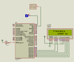
this cc code below for measure signal phase. i assign 4 square signals with freq=500 Hz,duty=25% to portb1,portb2,portb3,portb4.
i use portb0/int as trigger input.
when interrupt occurs at portb0 i read portb1...3 status. since for example portb1 is high i activate timer1 (T1CON.f0=1 ;) when portb0 becomes low i put T1CON.f0=0 ;.
then read c0= TMR1L; i0= TMR1H << 8; z0= c0+i0; but its all zero at lcd
 

Attachments

  • code test.rar
    72 KB · Views: 50

You can read only one input at a time because same TMR1 is used for all inputs PORTB (1 to 4). RB0 is trigger. You should do like this. Say for RB1. When RB1 goes high you start timer1 and wait till RB1 goes low. Once RB1 goes low you stop timer1 and get the TMR1H and TMR1L values. You can't read all channels simultaneously.

You can use RBIF and based on which pin caused RBIF you can start timer1 and get the value but again only one channel at a time. You should have 4 switches on RB4 to RB7 and RBIE set. when switch 1 is closed then RB4 will get triggered if RB4 goes high then you start timer1 and wait till RB4 goes low then you stop timer and read the timer value. Then you change switch and find do similar with some other channel.
 
the problem is that the TMR1H and TMR1L values always zero
 

How are you testing ? When do you make RB0 high and how ? What happens if you make RB0/INT0 high and RB1 is not yet 1 ? The execution would have finished the ISR routine by then. What happenes if RB1 is high (5 ms elapsed after high) and then you make RB0 high ? From what time it gets TMR1 value ? The moment INT0 fgot triggered ?

It is working. You have to do some calculation. You are calculating frequency and not phase.

112260d1418364193-phase.png
 

Attachments

  • code test.rar
    137.2 KB · Views: 47
  • phase.png
    phase.png
    35.8 KB · Views: 78
Last edited:
Status
Not open for further replies.

Similar threads

Part and Inventory Search

Welcome to EDABoard.com

Sponsor

Back
Top