thranduil
Member level 1
Hi all guys,
I am trying to make an oscillator using CMOS inverter for quite some time and it won't oscillate at desired frequency.
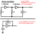
I want to make 125 KHz oscillator using following schematic (the element values are not relevant for desired frequency):

The circuit simply won't oscilate for every combination of L and Cs. I am aware that inverter provide -180 phase shift. So, the feedback circuit should provide also -180 degree and it should work if the loop gain is higher than one. I have L of unknown value (at th emoment it is a secondary of a 220 to 12.6 V transformer), and capacitors are of 1 nF. In this configuration oscillations have frequency of 1 MHz. As soon as I change to another secondary (for 6.3 V and less) it doesnt oscillate. So, how can I debug this?
Thanx
I am trying to make an oscillator using CMOS inverter for quite some time and it won't oscillate at desired frequency.
I want to make 125 KHz oscillator using following schematic (the element values are not relevant for desired frequency):
The circuit simply won't oscilate for every combination of L and Cs. I am aware that inverter provide -180 phase shift. So, the feedback circuit should provide also -180 degree and it should work if the loop gain is higher than one. I have L of unknown value (at th emoment it is a secondary of a 220 to 12.6 V transformer), and capacitors are of 1 nF. In this configuration oscillations have frequency of 1 MHz. As soon as I change to another secondary (for 6.3 V and less) it doesnt oscillate. So, how can I debug this?
Thanx