Continue to Site

Welcome to EDAboard.com

Welcome to our site! EDAboard.com is an international Electronics Discussion Forum focused on EDA software, circuits, schematics, books, theory, papers, asic, pld, 8051, DSP, Network, RF, Analog Design, PCB, Service Manuals... and a whole lot more! To participate you need to register. Registration is free. Click here to register now.

Help need to resolve Wire Connecting Problem in Agilent ADS2011.10

Status
Not open for further replies.

narayani

Full Member level 2
Joined
Aug 15, 2014
Messages
120
Helped
0
Reputation
0
Reaction score
1
Trophy points
1,298
Activity points
2,262
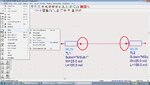
I am using the Agilent Advanced Design System 2011.10(ADS2011.10) for my work. I am facing the problem of wire connecting between Two MLINS or MLIN and MSBEND or something else. Whenever I use the Wire, I am getting the Red lines between Wire and MLIN or Wire and MSBEND. Even I tried to remove the red using EDIT > MOVE > MOVE WIRE END POINT, I am unable to remove the redlines.
Can you anybody help me remove remove red between wire and other components using ADS2011.10.
 

Attachments

  • Red_Symbols_While_Connecting_Two_Wires.jpg
    Red_Symbols_While_Connecting_Two_Wires.jpg
    233.1 KB · Views: 305

It's a grid problem.While you are moving it, snap the component from its pin, not body.
 
It's a grid problem.While you are moving it, snap the component from its pin, not body.
As you told I did it, I am getting. Earlier this grid problem was not there while connecting wire to other elements, now I am facing this red symbol while connecting wire to other components.
How to get rid of this grid problem without snap every time, we need to connect wire to other components. Can you help. Earlier without using snap the component from its pin, I was easily connecting wire to other components without getting red symbol.
What changes we have to make, just by connecting wire to other components without getting red symbols without using snap option. Can you help me.
If you drag the component from its pin instead of body, you will be put it on the grid.If you would to arrange the grids, please check the prefeences and adjust the grid properly.
Then you can connect them without any trouble..
 
In the schematic window open the preference editor, Options > Preferences... Then in the Grid/Snap tab make sure the Enable Snap option is checked. Usually, the Pin and Grid snap to options are checked also. The Vertex snap mode is not usually necessary for schematic editing.

If these options are checked any new editing done in the schematic should connect correctly.
 
Status
Not open for further replies.

Part and Inventory Search

Welcome to EDABoard.com

Sponsor

Back
Top