Continue to Site

Welcome to EDAboard.com

Welcome to our site! EDAboard.com is an international Electronics Discussion Forum focused on EDA software, circuits, schematics, books, theory, papers, asic, pld, 8051, DSP, Network, RF, Analog Design, PCB, Service Manuals... and a whole lot more! To participate you need to register. Registration is free. Click here to register now.

Temperature variable gain

Status
Not open for further replies.

BrunoARG

Full Member level 4
Joined
Aug 15, 2014
Messages
214
Helped
38
Reputation
76
Reaction score
38
Trophy points
28
Location
Buenos Aires, Argentina
Activity points
2,177
Hello everyone.

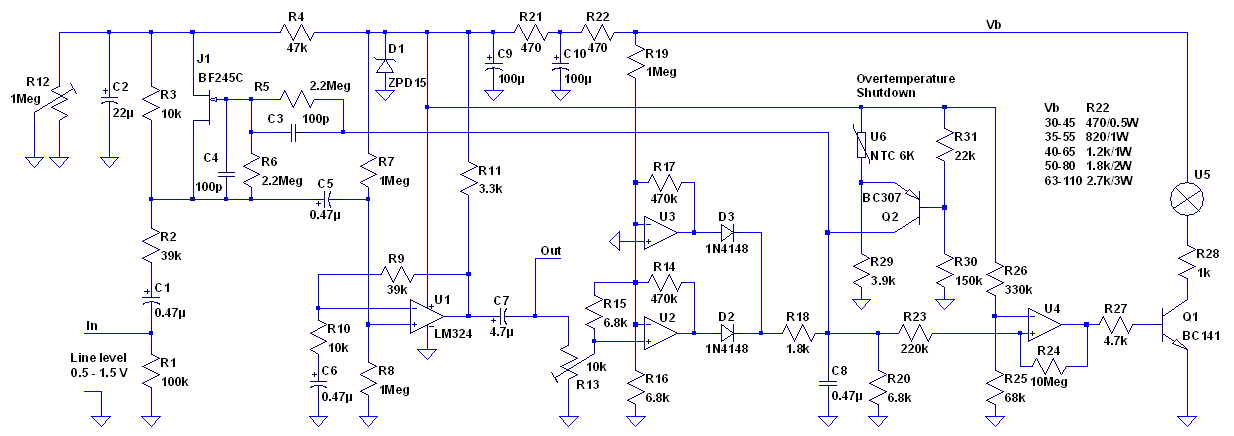
I am designing a medium power audio amplifier which is likely to heat up as every power driver.

What I want to do is an analog variable gain amplifier which decreases its gain when the temperature rises. It will be useful to protect the amplifier driver from burning due high current.

The problem I come up with is how will I make an analog variable gain amplifier. I thought about an opamp backfed with a FET transistor, which RDS would vary according to a gate voltage. The problem is that the gain/temp would not be linear.

Other way I found to solve the problem is a NTC connected as feedback resistor coupled to the heat sink. When it gets too hot the gain would decrease till stabilize in a safe working output voltage.

I have a doubt with those variable resistance devices non-linearity. Could it affect the amplifier working? could it generate any distortion? Is there another way (commonly used) to protect amplifiers from burning? I thought of a zener limiting the input voltage but it will certainly generate distortion at a point.

Thank you in advance.
 

Common protection means are current limiting to protect against output shorts and overtemperature shutdown. A well designed audio amplifier shouldn't get overheated with any usual audio input.

I don't believe that variable gain is an appropriate means against overload. If the user want's it pretty loud, he'll turn the volume control though.

A useful field for variable gain is a peak limiter that cuts the audio level before the amplifier is overdriven and generates weird distortion. A good way to protect speakers and also peoples ears.
 

An audio amplifier may heat but will not burn or suffer any damage. I want to protect both speaker and amplifier IC from burning.

If I use a peak limiter (very simple indeed) the amplifier will generate a very annoying distortion. What I want to do is to decrease de gain till the point that it doesn't generate distortion but it gives the maximum power, it's a kind of automtic volume regulator.

I really care about both signal quality and device safety. That means don't allowing the amplifier to distort and to be damaged due to overload. I've designed it to work with 4 ohms maximum giving a maximum power of 7W (if I made calculations well).

By the way I am using two bridged TDA2030 at +14V. I've been reading and it seems to be reliable and wouldn't generate too much distortion.
 

Seems like overkill. The amp should be heat-sunk well enough so it won't overheat at maximum volume and maximum ambient temperature. If the amp is distorting, just turn down the volume.
 

The TDA2030A has a minimum supply of 12V so your 14V is close. It works well with a high supply voltage and an 8 ohm load. Your bridged 4 ohms will appear like a 2 ohms load to each of your bridged ICs.

7W into 4 ohms is a signal level of 5.3V RMS which is 15V p-p. Then each of the bridged amplifiers must produce 7.5V p-p.
The TDA2030A has a high voltage loss so I do not think it will work bridged driving a 4 ohm load with a 14V supply.

Some bridged amplifier ICs for car radios might still be available.

All of these amplifier ICs automatically keep their idle current constant as they warm up. They also shut down if they get too hot.
 

What I want to do is to decrease de gain till the point that it doesn't generate distortion but it gives the maximum power, it's a kind of automtic volume regulator.
Makes more sense than what you asked in the first post. It can be made e.g. with a JFET as variable gain element. Because it's essentially a feedback controller, the JFET type and temperature variations don't affect it's operation.
 

The FM radio stations that play POP music in my area want to sound louder than is possible so they turn up the volume and use a limiter to keep the music peaks at maximum allowed power. Then there is a very obvious pumping effect where the background music volume is cut each time there is a loud bass beat and the bass beat is not as loud as it should be. It sounds awful. Is that what you want?

A linear amplifier heats the most when its continuous output power is about 70% of the power where it begins clipping. When its volume is turned way up then it cools because its output transistors are no longer linear but are switching on and off.
 

An input temperature controlled attenuator may protect the amplifier.A sophisticated solution can be found with a simple heat sensor+control unit.
But moderm power amplifiers are protected against overload ( and temperature ) on relay based solution.When the heat rises up to limit value, the control circuit cut-off the supply voltage and the output simultaneously.It seems more robust.
I'm wondering why output stage heats up driver circuitry ?? There should be an electrothermal design error.Otherwise a driver will continue to drive the ouput stage even this stage is overloaded by any cause..
 

Thanks for all the responses.

When I mean 'heat' I mean it gets a bit hot but won't burn up the amplifier ICs (that's what should happen). If it gets so hot (due to overload) it could turn off as protection, actually it's an effective solution but as Audioguru said, a peak limiter sounds awful and a relay would turn the speaker off.

I understand your solutions but they will turn the amplifier off or generate distortion.

My idea is to reduce the volume to keep the maximum power (as the user would want) without distortion (measuring input signal and controlling the gain) and without overheat (just controlling the gain with a temperature sensor).

Is using a NTC to control the volume depending of the sink temperature a bad idea since its non-linearity? I still have no effective ideas to remove high peaks... Maybe a logarithmic amplifier or audio compressor? Could it work?.
 

See below the circuit of a peak limiter that I designed a long time ago. It reduces the audio level before the amplifier clips, dynamically adapted to power the supply level, using a JFET as variable gain element.

It also includes a thermal shutdown controlled by a NTC mounted on the heatsink.


I also recall designing an AGC microphone amp using a FET as a voltage control attenuator with 40 dB control range. However in this situation to limit power, you shouldn't need more than 10 dB attenuation.

First off, I would recommend you consider temperature controlled fan cooling and use that to control the voltage on a pair of thick fans that run at low RPM with turbulent air over the hotspots removing the air with a plenum...
In my designs, I used a 3 terminal LM317 with a thermistor epoxied to hotspot, and a pot for setpoint , a resistor divider for range control and small transistor to bias the ADJ pin to control the fan speed from Off to full speed ( e.g. 45~55'C)

Second , these days a dual OTA can be used as a high quality pre-amp with over 60 dB range, which is overkill, but can be reduced to < 10dB range by limiting the control range.

You will need to define your transfer function first for attenuation vs temperature then temp vs R then R vs V and you can make it flat then ramp down with rising temp with a controlled slew rate.

The dual OTA LM13700 runs off +/- 15V for use as a pre-amp..

OTA.png
 

An OTA can work as variable gain element, but as a disadvantage, it generates relevant THD without gain reduction while a FET attenuator doesn't.
 

I think that a FET would be cheaper. Which one do you recommend to use? JFET or MOSFET? They are both non-linear but how should I calculate the RDS value? I've been searching and the more I read the more confussed I get.

Is there a way to make RDS variation more linear? I think it would be possible with a resistor connected in parallel to the FET drain and source. A simple non-inverting op amp amplifier with the variable resistor as feedback must work.
 

Status
Not open for further replies.

Part and Inventory Search

Welcome to EDABoard.com

Sponsor

Back
Top