Darius Baronas
Member level 3
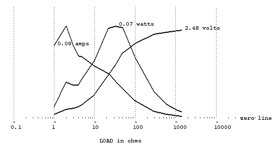
Hi all. I'm new with solar panels. Can I calculate output voltage and current , if I know, that Voc=7V , Isc=0.33A , and load is 30 Ohm ? The source resistance i think is R=7/0,3=23.3 Ohm. Thanks !
Follow along with the video below to see how to install our site as a web app on your home screen.
Note: This feature may not be available in some browsers.
")
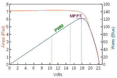
Review the varying solarcell I/V characteristic with different irradiation levels. https://en.wikipedia.org/wiki/Mppt
For each irradiation, there's one maximum power point. MPPT is the method to find it.
I'm reading about MPPT now, and i'm thinkink : do MPP tracking needed only for solar panels, because they have varying impedance depending on light, or MPPT is needed for all energy harvesting methods such as thermo, wind, piezo etc. ?
When i read about MPPT there are always buck, boost, or buck-boost controlled by pwm. I read but still do not understant principle of load matching. Lets say we have irradiance, when solar panel output is Voc=6V , Impp=0.2A (Lets say 1W at mpp) . And i connected straight to the battery with 3.3V voltage, what i got now ? 3.3V ,0.2Amps and 0.66W power ? How to increase extracted power with dc-dc ? Please explain in simple words..
Power from solar cell = 1W, so if converter is 100% efficient, then 1W will go into your battery, so at 3.3V, current = .3A. If converter 90% efficient the current int battery will be .3 X .9 = 2.7 A
Frank
So if there are 1W (5V and 0.2A) current at mpp, and the battery is 3.3V , buck dc-dc regulator (100% efficiency) should work with 66% duty cycle, then voltage 5*0.66=3.3V , current 0.2/0.66=0.3A , and 1W goes to the battery ? And if there are no dc-dc, then we have 3.3*0.2=0.66W , right ?
You'll need another topology than a buck converter. It will not give you more current out than you have going in.
actually Buck mode boosts DC average current from Cap discharge. So Power transfer is constant and current ratio is inverse to voltage ,
but multiply x by efficiency. (Typ 90%)
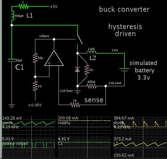 Want to do same simulation using simulink or multisim..
What is that app with simulation window? Looks like android app, interesting