Continue to Site

Welcome to EDAboard.com

Welcome to our site! EDAboard.com is an international Electronics Discussion Forum focused on EDA software, circuits, schematics, books, theory, papers, asic, pld, 8051, DSP, Network, RF, Analog Design, PCB, Service Manuals... and a whole lot more! To participate you need to register. Registration is free. Click here to register now.

trigger on peak in AC waveform

Status
Not open for further replies.

yougarage

Member level 1
Joined
Apr 13, 2011
Messages
38
Helped
0
Reputation
0
Reaction score
0
Trophy points
1,286
Activity points
1,599
Hi! I need to trigger an interrupt in a microcontroller when a AC signal reaches the top peak value.
The AC signal I'm talking about, vary in frequency (20 - 200 Hz) and voltage (500 - 1000 V). It comes from a generator, when it turns faster, the frequency and the voltage raise.
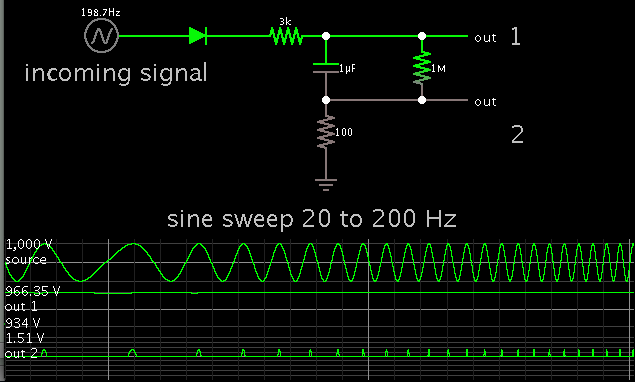
I thought of a simple circuit as shown in this picture. It is also shown the trigger point on the waveform. It should output a falling edge when the top is reached.
What do you think about it? Which capacitor value for C1 would you go?
Any advice is really welcome!
trigger.jpg
 

Because of the high value of R1, the incoming "voltage" is actually more like a constant current , the output will be more or less a square wave -.8V -> +5.8V P-P.
The problem is that at the peak of a sine wave, nothing much happens, it goes from 99% -> 100% - 99% of the peak voltage. I would use a single hi gain NPN transistor, use a 10K collector load, feed its base via a very small capacitor from your AC, and wire a diode, cathode to base, anode to earth to protect the transistor.
The current through the cap, is leading the voltage by 90 degrees, so at the peak voltage, the current actually goes from negative to positive which will switch the transistor on. If you just need a narrow pulse feed the square wave via a capacitor and a pull up resistor.
Frank
 

An alternative method, assuming the voltage is stable over at least a few cycles, is to rectify and reservoir it so you have the peak stored as a low frequency signal then use a comparator to detect it falling slightly. You can try it in the frequency domain too, assuming the generator cannot instantaneously change speed (it accellerates and decellerates) you can measure the cycle period and assume the next peak is half a period from zero crossing.

Brian.
 

Thanks for your suggestions. The generator accelerate and decelerate fast, so I cannot use betwixt's solution. The signal is from a flywheel-magneto of a engine.circuit.jpg
this is the circuit suggested by chuckey. Would you go for a Darlington transistor? Should I limit the base current in some way?
 

The peak is the worst place to trigger, the flat-top's
nil dV/dt means dT (which becomes jitter or timing
error) responds hugely to noise and not much to the
real signal.

Back in the day, doing SCR motor drives, we used to
first differentiate the signal and then trigger off the
zero crossing - equally valid, better quality signal (and
stripped of much HF line noise by the op amp's slowness).
 

I know the peak is a bad place to trigger, but I'm stuck with this. This is a capacitive discharge ignition unit from a small engine. The magneto output this signal only, it is used for both charging the capacitor and for timing. The low spike at the top of the wave is probably noise induced by the spark.
idle.jpg
high_rpm.jpg
I want to replace the stock unit with a custom made one, so trying to understand how the stock one reads the signal could be the key. Each AC cycle is one revolution of the engine.
 

bc547_103_revving.JPG
bc547_102_revving.PNG
Hi, I just made some tests. I tested with a BC547 NPN I had laying around.
The two pics refers to different capacitor values (based on the schematic 3 posts ago).
I found that a 103 cap produces ringing, probably the base current is too high. I then tested a 102 cap, and works fine. I also tested a 22pF cap, but the signal is weak at low frequency. The next test will be a 22 pF cap with a darlington transistor.
 

I'm sure there are many ways to solve the problem, but the decision would be always based on detail informations that are missing in your posts yet. You say e.g. the frequency range is 20 to 200 Hz which sounds less than perfect for an ignition unit that should preferably work from "zero" speed upwards.

Other points are noise and possible waveform distortion. The post #6 waveforms looks quite different from idealized post #1 and also post #7 waveform. I would start with the question which signal characteristics are robust and which prone to variation. Rather formally, the signal peak can be e.g. determined as zero crossing of signal integral. But also a zero crossing detector in combination with a digital period measurement and delay can work.
 

For an arbitrary periodic waveform, it is impossible to trigger on the peak, if by "triggering on the peak", you mean detecting the peak and starting something (like a scope trace) in real time. The reason is that you cannot tell you are at the peak until you see some lower values later to confirm that it is a peak. But by then it is too late. So arbitrary waveforms are out of the question.

Fortunately, most applications (and probably yours too) are not composed of arbitrary waveforms. So you can use the knowledge of the properties of that waveform to construct a custom circuit that will trigger on the peak. For example, if the waveform is a sine wave, you can phase shift is 90 degrees and trigger on the zero-crossing of the cosine wave.
 

Here is a simple concept to get a pulse output when the incoming sinewave is about to peak.

It can work with your 500-1000 V input amplitude. The capacitor can charge to any level. It drops a few volts during the idle gap between sine peaks.


Status
Not open for further replies.

Part and Inventory Search

Welcome to EDABoard.com

Sponsor

Back
Top