Continue to Site

Welcome to EDAboard.com

Welcome to our site! EDAboard.com is an international Electronics Discussion Forum focused on EDA software, circuits, schematics, books, theory, papers, asic, pld, 8051, DSP, Network, RF, Analog Design, PCB, Service Manuals... and a whole lot more! To participate you need to register. Registration is free. Click here to register now.

Circuit design for exponentially decreasing voltage with current

Status
Not open for further replies.

AshwinNambiar

Junior Member level 1
Joined
Oct 21, 2014
Messages
16
Helped
0
Reputation
0
Reaction score
0
Trophy points
1
Activity points
151
want to design a circuit on NI MULTISIM which is like:
The input voltage of around 100 to 150 V and input Current 10A;
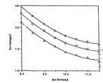
The circuit designed should be such that at the output i need an increasing current with the decrease in voltage;in other words the motive behind the circuit design is to have an EXPONENTIALLY DECREASING curve of voltage to current.
Also i want to know how to plot voltage Vs current graph on NI MULTISIM,i get a voltage Vs time graph or current Vs time graph but i require a Voltage Vs current graph ,please advice how;also the circuit design for the exponential decreasing curve of the same would be helpful.I've tried with least success.A beginner trying to learn these.Please help.
 

I do not understand what you want. Given, Vin = 100 V, At Io =0A, Vo =?, at Io = 10 A, V0 =? Or, Vin = 150, Io =0, Vo =? and Vin = 100, Vo = 100 at Io = 10A.
Can you not give us a table of Vin against what you expect at the output. The exact law can be ignored because we know its exponential.
Frank
 

Suppose you charge a capacitor through a 10 ohm resistor, at 100V...

The capacitor will start out at 10 A, 0V.

Eventually it will have 0A, 100 V.

The amperage curve will drop. The voltage curve will rise.
Each will have the familiar shape.
 

If say Vin =130V,the circuit should be designed in such that at the output Io increases with a decrease in Vo.The graph is plotted with Vo against Io,which is an exponentially decreasing curve of Vo Vs Io.
Eg:
Vin=130v;Vo=125v;Io=10A
Vin=130v;Vo=122v;Io=11.5A
Vin=130v;Vo=120v;Io=14A
Vin=130v;Vo=114v;Io=12A

Input voltage is a constant 130v DC,the circuit designed should give an increase in the current with a decrease in voltage and thus the graph of Vo Vs I0 is plotted which is an exponentially decreasing one.
I believe i've been clear this time,looking forwad for your help
 

An inductor creates the curves you're talking about.

Charge it through a 10 ohm resistor.

**broken link removed**

Yellow is amperes through the inductor. Green is voltage across its ends.
 

m trying to simulate an electric arc using non-linear active load on NI MULTISIM or PSPICE .The electric arc is such that the current increases as there is a decrease in the voltage;when plotted on a graph we have a negative resistance slope,an exponentially decreasing voltage with increasing current.
I want to design an electronic circuit,simulate it, which gives me the same plot of voltage Vs current as for an electric arc.
The purpose is to design a circuit which shows the simulation of electric arc using non linear active load.
I have attached an image of the V-I characteristic of an electric arc.Now,I'm looking to design an electronic circuit which gives me a similar plot,thereby calling it an electric arc simulator circuit.
 

Attachments

  • VI characteristic.JPG
    VI characteristic.JPG
    43.5 KB · Views: 100

Vo= 120@ 14A is just an estimation to the set of values mentioned to help understand what i exactly need.
The purpose for me asking this is i've taken baby steps to working on an arcjet thruster load.What should be done is:
1.Designing an electronic load such that it gives me an output characteristic similar to that of the arcjet thruster load i.e an equivalent electronic design
2.There is this specific characteristic of arcjet thruster that the arc when created has static VI characteristic(negative resistance slope),the target is to achieve the same for an electronic load design.
I could download a paper on the same but the problems faced:
1. The circuit designed has many of it s components obsolete.
2.The paper is as old as published in 1991
3.I'm unable to get an equivalent of the components that are obsolete.
I went about with the literature and trying to come up with a new design of the electronic load,the aim being to achieve the same V-I characteristic.
The link to the paper, https://ntrs.nasa.gov/archive/nasa/casi.ntrs.nasa.gov/19920008291.pdf

Page no.3,shows the characteristic and page no.11 has the circuit design with the then existing components.I'm not looking to do everything that is in the paper,just the electronic load design with the above mentioned characteristic.

Looking forward for help,guidance and suggestions.
 

I made a circuit that draws less current as supply V goes up.

Its graph is similar to your post #6, although mine has straight lines (whereas your graph has curved).

**broken link removed**

The left-hand transistor reduces the bias on the load transistor.
As supply V increases, it pulls it down disproportionately more.

Adjustment of the potentiometers is extremely delicate.

The supply V varies between 110 and 130 V.

The rightmost transistor carries a kW of power.
 

Status
Not open for further replies.

Part and Inventory Search

Welcome to EDABoard.com

Sponsor

Back
Top