Continue to Site

Welcome to EDAboard.com

Welcome to our site! EDAboard.com is an international Electronics Discussion Forum focused on EDA software, circuits, schematics, books, theory, papers, asic, pld, 8051, DSP, Network, RF, Analog Design, PCB, Service Manuals... and a whole lot more! To participate you need to register. Registration is free. Click here to register now.

[SOLVED] Zero crossing to pic from 24 VAC with 2n2222

Status
Not open for further replies.
Thank you Paul.
I did some experiments on Proteus - I hate this software but is the only i have - and here are the results
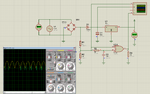
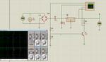
On 2N2222 is a nice clean signal
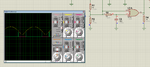
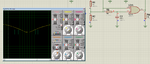
On XOR version, i have some spikes on the begining and end of the pulse.
Maybe is Proteus
Can anybody test it with other software ?
Thank you
 

Attachments

  • XOR.png
    XOR.png
    130.9 KB · Views: 59
  • 2n2222.png
    2n2222.png
    131 KB · Views: 61

Hi,

regarding your post14.
Sorry for being so late. But you don´t need a true voltage divider. Like to measure voltage. If you ise it this way you won´t get sharp signal.

regarding your post16:
there are 74HCT1G14 in small SOT23 or even smaller SOT70 package. It is a s small as your 2n2222 bjt.

Or SOT23 comparators. here you can adjust the trip level the most accurate.

Klaus
 
Thank you Klaus,
Can you look at post 21 and tell me if the version with XOR is correct ?
Yes, they have it in 1 gate single package like you said
Maybe i use this instead of 2N2222
But i have a glitch or it is just on my computer scope .
I do not know yet as i do not have parts under my hand to test

- - - Updated - - -

Can somebody help me to get the proper values of R an C to get a CLEAN 1 ms pulse
I tried various values and always end up with spikes on front and end of the puls like in the attached pictures
thanks
 

Attachments

  • spike1.png
    spike1.png
    97 KB · Views: 61
  • spike2.png
    spike2.png
    93.9 KB · Views: 60

if you use a simple RC, you introduce a suplementary delay, so not exactly synchro with zero .
and orginal pulse must be longueur than RC delay..

You can use this monostable version with NOR circuit ( or canbe also done with XOR)
you get a pulse longuer than original and calibrated to 1mS

CMS version of 2n2222 is very small...

Capture.JPG
 
Thanks Paul,
How to set a scope in circuit maker ?
Is it anything wrong with my xor version ?
What i try to achieve here is space and clean signal
For clean signal i got options.
Using just one gate xor solve me the space problem
Using two gates like you suggest, it goes out of the PCB
The PCB is already crowded with 601 components on 4 layers
It is very small and it will replace a previous version. As the plastic molding stay the same, the PCB must stay the same size and shape.
Believe me that i do not want o upset everybody and shows my ingratitude, but i have constraints which i cannot change.
So, using just o voltage divider form bridge, i get input for :
Inverter = nice clean signal but equal on 1 and 0 side
XOR = nice pulse, adjustable, but with noise on both ends
I would like to have the 1 gate XOR but with a clean signal.
I am not expert in analog, but i have to use it.
 

Hi,

first put a probe on the input of the voltage divider. Then you see the input signal. With all the distortions coming from the leakage inductance, diodes, their capacitance and their recovery process.
change your circuit (make it low ohmic) to get a clean signal here. After this you can go to the next step.

Then decide what circuit to use.
* 2N2222 (cheapest, should work, but not that sharp edges, but sharp enough for ucontroller input)
* XOR (i don´t think this gives a single shot at zero cross. it gives a pulse before and one after zero cross, --> four for a complete full wave)
* OR, NOR AND, NAND (logically it think you need an inverted and a non inverted input. not available)
* single schmitt trigger HCT1G14 (because of fixed threshold you have limitations on adjust)
* comparator (most flexible, most precise)

Your ucontroller should get an interrupt very near the ZC event (i recommend 200us before ... 50us after ZC). Only this one edge (either rising or falling, depending on your circuit) is needed. The pulse length itself is not critical

Klaus
 
Some MCU have trigerred input ...
it is your case ?

Don' t forget that you can also have some spike on AC rectified signal , comming from the AC nest (Moteur or neon light load)
Synchro signal must be keept clean.
Very simple circuit can not fit all cases.
 
Thank you Paul and Klaus
I will try to see results with real parts tomorrow when i get them from Digikey
But i ask again.
What values to use on the XOR version i posted to eliminate the before and after spikes at least on the simulator ?
Thank you
 

Hi,

in my eyes the signal at the top of the resistor divider is critical.
So i use two extra signal diodes (2 x 1N4148, or 1 x BAT54C) for the zerocross signal

Here the LTspice simulation.
with a 10Vp input signal the pulse width is 1ms.

zc.png

Klaus
 

Attachments

  • zc.bmp
    2.1 MB · Views: 60
Thank you Klaus
2 diodes it is an interesting approach
Please be so kind and attach the spice project as i have Ltspice on my computer
@Paul : How i attache the second probe on simulation of circuit maker.
Every time i touch the probe on different point it just move the first one and does not attach the second one
Thanks to all for help. I start seeing some light at the end of the tunnel. But is far yet
 

What values to use on the XOR version i posted to eliminate the before and after spikes at least on the simulator ?

i think simulator can't work correctly because :
for the 74LS86 TTL LS serie, you are using values dedicated for CMOS circuit .. wrong values, too big
try to Decrease Resistor value <= 5K and increase capacitor ..

How i attache the second probe on simulation of circuit maker.
press and maintain SHIFT key and click on the other point to check with scope
 
Thank you very much Paul
I did not pay attention at ttl or cmos. My fault
Changed the input to 2.2 volts and no more spikes
Thanks for the hint on scope probes.
 
Last edited:

Hi,

here the zipped asc file.


Klaus
 

Attachments

  • Zc.zip
    728 bytes · Views: 61

All digital input has a trigger.

it is not true for all input..
some of them are specified in datasheet
for example RA4 is a shmitt trigger input, not the other on PORTA 18F46K22


I have no idea what are you doing here, guys. He needs only npn transistor and resistor. The zero catching by sw.


The start of this post was about an Hardware request ...
I know there are other solutions
like the use of internal comparators wich can fire an interrupt when signal input comes upper or lower than defined threshold .
With RB0 interrupt also, but signal input must be clean..

and we don't know how he plan to handle this signal by software...
 

There are three processes to produce a variable crossing pulse in hardware for Triac phase control for controlling a motor. I will talk about the 1st two.

1. Zero crossing of voltage , ZVC (both directions converted to unipolar pulse)
2. variable dwell or pulse width modulation up to 100%
3. Zero crossing of current switch , ZCS, which will lead voltage for an inductive load , but determines when precise firing of Triac may begin for 100% switching for next cycle, as Triacs turn off at zero crossing of current and turn on with a pulse or >2V applied to input. The pulse method is most accurate.


One is to use a "limiter" or "slicer" on a sine wave to make a perfect square wave then the fast edge may be delayed with a gate or RC delay and compared with a 2 input XOR gate to produce a narrow pulse. this can be done just as easily in firmware.

The second method has to slice the rectified AC near the minimum voltage when the diode bridge goes into high impedance mode and the transistor or comparator is very sensitive to noise pulses or ripple near the zero crossing point. This method works in theory, but is very open to false triggers near the zero crossing point.

The real problem is noise immunity and how to reject false triggers.

One method is PLL with narrow tracking filter, (best) another a gated window to disable more pulses until after 95% window delay to allow for 5% frequency increase ( works but still prone to jitter) and then simple transistor amplifier on rectified AC which is prone to gain error from voltage divider and offset error of transistor Vbe threshold, which leads to a pulse that starts before and ends after the true zero crossing, and due low SNR, the ripple may produce extra pulses.

Once you understand this analog concept and how to best detect frequency and phase in the presence of noise, you will appreciate that using a the diode bridge is a crude method, not reliable without special filters since the ideal rectified signals spans many harmonics.

Using a pure sine wave a filtered input or a simple PLL, with a slow tracking filter gives one the perfect noise immunity so you can then have a cleaner pulse to determine variable dwell for phase control.

Implementation is meaningless, until you understand the quality factors of false detection, false switching with leading current and radiated and conducted false triggering of Triacs. We are not talking about a controlled lab signal with a resistive load, but a dirty noise environment with fast rising Triac load switching and motor surge currents.


OK? Which way do you prefer cheap and dirty? Or clean and reliable but more complex.
 

Easyrider. Classic mistake to ignore motor ripple and nonlinear loading effects.

you are assuming ideal voltage source with 0 ohm source and no other capacitive or inductive loads with spurious dumps from speed change.


Of course, if you put a large plastic or ceramic low ESR cap across the transformer to lower the impedance to spurious noise and use a separate bridge for DC and for this ZCS detector , it might work better, but still poor noise margin and false triggering implies a potential large motor surge.
 

Sure, add RC integration chain if you wish.
- integration adds phase shift , and storage cap suppresses zero crossing due to peak detector effect. Load R to ground needed first.

Still low grade in presence of commutation noise from motor for which this pulse is used to control speed by phase control, but possible to work with more effort.
 

Status
Not open for further replies.

Part and Inventory Search

Welcome to EDABoard.com

Sponsor

Back
Top