kerrytang
Newbie level 4
Hi guys, I have a problem about the stability of positive feedback.
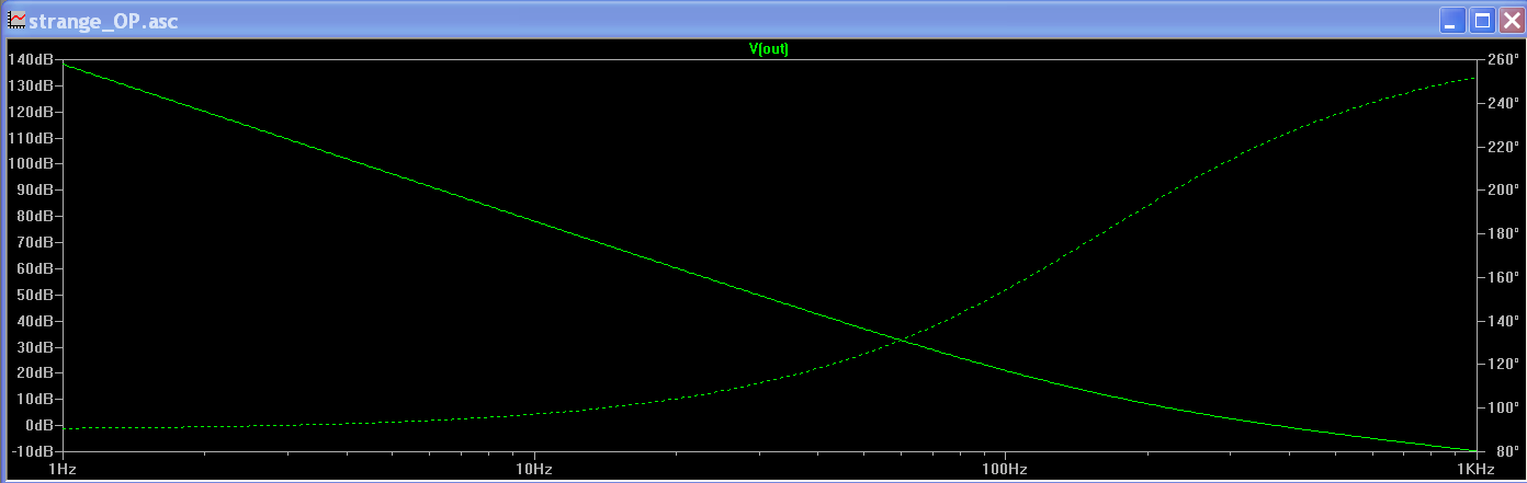
Let's say for a opam, it has 3 poles (LHP) at DC and 2 zeros (LHP) at wz. Then at DC, its phase shift is -270 degree , and at wz, its phase shift is -180 degree. At wz, its gain is 4.
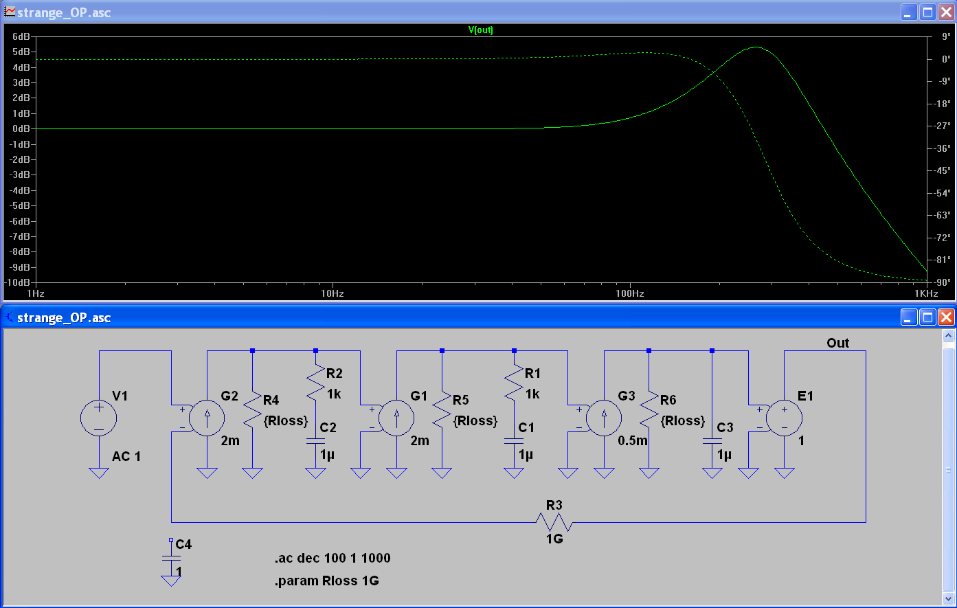
Then we connect the opam in a unity gain negative feedback structure.
The phase margin of this loop is -90 degree and it should be stable. But at wz, the phase shift of this loop is -180 degree and has gain of 4, it looks like adding its feedback signal to its input signal in phase, just like a positive feedback. So why this it acts like a positive feedback but it is still stable?
Can anyone give a intuitive explanation, thanks a lot.
Let's say for a opam, it has 3 poles (LHP) at DC and 2 zeros (LHP) at wz. Then at DC, its phase shift is -270 degree , and at wz, its phase shift is -180 degree. At wz, its gain is 4.
Then we connect the opam in a unity gain negative feedback structure.
The phase margin of this loop is -90 degree and it should be stable. But at wz, the phase shift of this loop is -180 degree and has gain of 4, it looks like adding its feedback signal to its input signal in phase, just like a positive feedback. So why this it acts like a positive feedback but it is still stable?
Can anyone give a intuitive explanation, thanks a lot.