Ahmed Kh
Junior Member level 3
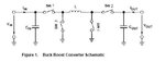
About buck boost converter in one circuit
Hello
please how can i design the buck-boost circuit
i have been designed as this circuit but the value of (l.r.c) hard to get it
i just want the equation if u have
my project about the variable input from(6-20)v and i have to get 12v output
my regards
Hello
please how can i design the buck-boost circuit
i have been designed as this circuit but the value of (l.r.c) hard to get it
i just want the equation if u have
my project about the variable input from(6-20)v and i have to get 12v output
my regards
Code: