rajesh279
Junior Member level 3
Hello All,
I am working on displaying day, date & time information on 7 segment LED using 74HC595 shift registers and COMMON ANODE configuration.
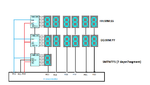
Please see my attached diagram. I am explaining the acrchitecture as follows:
1) The top row displays time in HH:MM:SS format.
2) The middle row displays date in DD:MM:YY format.
3) The lowest row (single 7-segment LED) displays Day of week. Each day coresponds to each segment in the 7 segment LED.
4) I am using 3 shift registers 74HC595, in which Clock & Latch lines are common. The Data is cascaded from one shift register to another.
5) I am getting the day/date/time values from RTC and extracted the DD:MM:YY, HH:MM:SS, DAY data to be displayed.
For display, I am following the below multiplexing technique: (Multiplexing using Timer 100 ms)
1) Switch ON PD5 (left most LEDs, i.e. 1st column, all the 3 rows) and remaining OFF.
2) Pull Latch LOW --> Shift out 3 bytes of data with clock --> Pull Latch HIGH.
3) Switch ON PD4 (i.e. 2nd column, all the 3 rows) and remaining OFF.
4) Pull Latch LOW --> Shift out 3 bytes of data with clock --> Pull Latch HIGH..
.
.
.So on ... till the 6th column.
I am facing below two problems:
1) Suppose, I activated the 1st column and shifting out 3 bytes data in this order:
[ Day --> Date(ten's place ) -- > Hours (ten's place) ].
All the digits are displaying at their corresponding rows in the 1st column, but in between, the Hours values is also getting reflected & flickering in the Date's place. i.e. Row 3 value is reflecting in Row 2 and Row 2 value is reflecting in Row 1.
This problem is associated with all the columns.
2) Because of the above problem, Row 3 (Day LED) is not reflecting the correct segment. .e.g if my Day value from RTC is 1, then only one segment should glow while others will be OFF, but all the segments are flickering.
For common anode , I am using ULN2803 for driving positive.
I checked my Timer is working fine, and I can increase/decrease the frequency, but I am not able to resolve the flickering/overwriting of one value on another.
I hope I am able to put my problem clearly. Can anyone of You Please help me on this?
My code is as follows:
I am working on displaying day, date & time information on 7 segment LED using 74HC595 shift registers and COMMON ANODE configuration.
Please see my attached diagram. I am explaining the acrchitecture as follows:
1) The top row displays time in HH:MM:SS format.
2) The middle row displays date in DD:MM:YY format.
3) The lowest row (single 7-segment LED) displays Day of week. Each day coresponds to each segment in the 7 segment LED.
4) I am using 3 shift registers 74HC595, in which Clock & Latch lines are common. The Data is cascaded from one shift register to another.
5) I am getting the day/date/time values from RTC and extracted the DD:MM:YY, HH:MM:SS, DAY data to be displayed.
For display, I am following the below multiplexing technique: (Multiplexing using Timer 100 ms)
1) Switch ON PD5 (left most LEDs, i.e. 1st column, all the 3 rows) and remaining OFF.
2) Pull Latch LOW --> Shift out 3 bytes of data with clock --> Pull Latch HIGH.
3) Switch ON PD4 (i.e. 2nd column, all the 3 rows) and remaining OFF.
4) Pull Latch LOW --> Shift out 3 bytes of data with clock --> Pull Latch HIGH..
.
.
.So on ... till the 6th column.
I am facing below two problems:
1) Suppose, I activated the 1st column and shifting out 3 bytes data in this order:
[ Day --> Date(ten's place ) -- > Hours (ten's place) ].
All the digits are displaying at their corresponding rows in the 1st column, but in between, the Hours values is also getting reflected & flickering in the Date's place. i.e. Row 3 value is reflecting in Row 2 and Row 2 value is reflecting in Row 1.
This problem is associated with all the columns.
2) Because of the above problem, Row 3 (Day LED) is not reflecting the correct segment. .e.g if my Day value from RTC is 1, then only one segment should glow while others will be OFF, but all the segments are flickering.
For common anode , I am using ULN2803 for driving positive.
I checked my Timer is working fine, and I can increase/decrease the frequency, but I am not able to resolve the flickering/overwriting of one value on another.
I hope I am able to put my problem clearly. Can anyone of You Please help me on this?
My code is as follows:
Code:
int main(void)
{
InitTimer();//initialize Timer for 100ms
InitPort();
while(1)
{} //infinite loop
return (0)
}
void InitPort(void)
{
DDRC = 0x00; //all as output port
DDRD = 0x00; //all as ouput port
}
void Switch_Column(unsigned char num_colum)
{
switch(num_colum)
{
   case 0:
   PORTD=0x20; // switch ON 1st column, PD5, and remaining OFF

   ST_CP_low();

   shift_out_byte(hrs_digit);
   shift_out_byte(date_digit);
   shift_out_byte(day_segment);

   ST_CP_high();
break;
   case 1:
   PORTD=0x10; // switch ON 2nd column, PD4, and remaining OFF

   ST_CP_low();

   shift_out_byte(hrs_digit);
   shift_out_byte(date_digit);
   shift_out_byte(day_segment);

   ST_CP_high();
break;
   case 2:
   PORTD=0x08; // switch ON 3rd column, PD3, and remaining OFF

   ST_CP_low();

   shift_out_byte(hrs_digit);
   shift_out_byte(date_digit);
   shift_out_byte(day_segment);

   ST_CP_high();
break;
   case 3:
   PORTD=0x04; // switch ON 4th column, PD2, and remaining OFF

   ST_CP_low();

   shift_out_byte(hrs_digit);
   shift_out_byte(date_digit);
   shift_out_byte(day_segment);

   ST_CP_high();
break;
   case 4:
   PORTD=0x02; // switch ON 5th column, PD1, and remaining OFF

   ST_CP_low();

   shift_out_byte(hrs_digit);
   shift_out_byte(date_digit);
   shift_out_byte(day_segment);

   ST_CP_high();
break;
   case 5:
   PORTD=0x01; // switch ON 6th column, PD0, and remaining OFF

   ST_CP_low();

   shift_out_byte(hrs_digit);
   shift_out_byte(date_digit);
   shift_out_byte(day_segment);

   ST_CP_high();
break;
}

}//end of function Switch_Column()
void shift_out_byte(unsigned char value)
{

unsigned char i;
for(i=0; i<8; i++)
{
          if( value & (0x01<<i)  )  // insert the LSB first
          {
             DS_high();           // If first bit is set, switch serial input high
            }
          else
          {
             DS_low();                    // Serial input (of 74HC595) low
          }

                SH_CP_high();                // trigger clock to shift if in.
              SH_CP_low();                // switch clock low again

}
} //end of function shift_out_byte()

void ISR_TIMER()
{
   Switch_Column(disp_column); //switcj ON each column at a time and shift out the data
   disp_column++;
   if(counter>5) { disp_column= 0;} // reset the counter

}