Continue to Site

Welcome to EDAboard.com

Welcome to our site! EDAboard.com is an international Electronics Discussion Forum focused on EDA software, circuits, schematics, books, theory, papers, asic, pld, 8051, DSP, Network, RF, Analog Design, PCB, Service Manuals... and a whole lot more! To participate you need to register. Registration is free. Click here to register now.

Reading 12 V battery voltage on Microcontroller Arduino Mega 2560.

Status
Not open for further replies.

QutabBaig

Newbie level 4
Joined
Oct 11, 2014
Messages
7
Helped
0
Reputation
0
Reaction score
0
Trophy points
1
Activity points
62
Hi

I wish to read a 12 V battery voltage on Arduino Mega 2560 ADC pin. To do that, there are two methods.

1. Use a voltage divider circuit.

2. Use an op-amp that would attenuate the voltage to keep it as low as 5 V like in given figure I m reading 14 V of battery by scaling it down to 4.19 V. My controller will read this 4.19 V as 14 V and I will do programming accordingly.
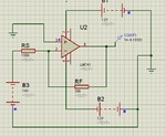
op-amp.png

Now the issue I m having is if I go with second method, do I need to worry about current. Is there any possibility that a large current may flow through op-amp towards controller and ending up burning my op-amp and controller? Is there any op-amp which can sustain high currents?

Pl assist
 

How much current can you push through a 100K resistor with 12volts?
 

Ohms law. 12/100 k = 120 uA

My application is Battery Charging through Solar Panels. So naturally current depends on rating of solar panel and other daylight conditions. I need to read voltage from Solar Panel as well.
If its a 40 Watt panel with 12 V output, it could give up to 3 A current.

Please correct me if I am wrong.
 

As you calculated, you can't push any more than 120uA through a 100K resistor at 12 volts, REGARDLESS of what the current rating of your source is. If that weren't the case, people would be electrocuting themselves with AAA batteries.
 

Okay.

Another question: Which method is better to read voltage. Via voltage divider circuit or attenuating voltage gain via amplifier?

Appreciate your kind assistance
 

It depends on the input impedance of your AD. If it's low impedance, the voltage divider method will contribute some error.
 

What is input impedance of ADC?
What and how does input impedance of ADC effect my reading?
If voltage divider method is not reliable should I opt op-amp method?

I m sorry for my stupid questions. My electronics is not very good.
Pl assist
 

I sure don't know what your impedance is; read the data sheet. The input impedance of the the ADC is paralleled with the resistor of your divider. So, sure, use the opamp.
 

Simplest solution is 30k from Vbat with 10k to ground gives 6:1 passive divider using 2.56 Vref thus full scale is 0 to 15.36V with a resolution of 2560/4096*6= 3.75 mV

Passive R divider is still low current using 10k across ADC port thus 6:1 divider using 50k series to Vbat is 15V/60k =250µA max.
If this is too much to your liking, buffer it with a NON-Inverting unity gain OA, not the inverting one you chose.

background info and other methods...
You have many options for this ADC and no OA buffer is required.


• 10 bit ADC
• 0V - VCC ADC Input Voltage Range
• 2.7V - VCC Differential ADC Voltage Range
• Selectable 2.56V or 1.1V ADC Reference Voltage
• 4 Differential Input Channels


You cant use single ended input and scale 14V=4.19V because this exceeds internal Vref options


Remember that Vref internal is the full scale ADC output $03FF.


Status
Not open for further replies.

Part and Inventory Search

Welcome to EDABoard.com

Sponsor

Back
Top