maltese001
Newbie level 1
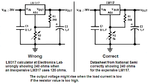
Hello guys, I'm fairly new to electronics so this might be a straight forward question. I was planning to build my own simple power supply using an old printer power adapter and an LM317 as a positive voltage regulator and an LM337 as a negative voltage regulator. The printer supply has 3 outputs.. 32V, 15V and GND. The power supply is only about 20W and the two outputs are rated to supply about 500mA.
My plan was to consider the 15V output as my reference/ground.. therefore i would have a +17V supply and a -15V supply (hence i'll be using the LM337 so the "new ground" line would be unaltered). I started off by testing my approach by building the +ve supply using the LM317... I built it using the datasheet and many guidelines found on the internet.. the designs are all the same and I have altered nothing. Using this configuration with the 15V as GND and the 32 V as my +ve the supply does not work properly. The voltage drops on load and sometimes it also seems to be oscillating. At first i suspected that i was misusing the LM317 but then i tried the same setup, this time connecting to the proper GND and +32V and the supply worked fine, even on load.
I am therefore suspecting that the problem might be coming from the printer power supply itself and was wondering what it might be and if there might be a solution to it. Thanks a lot : ) This is the link of the circuit diagram... its all the same using (the .1uF capacitor is ceramic and the 1uF is electrolytic) : **broken link removed**