Continue to Site

Welcome to EDAboard.com

Welcome to our site! EDAboard.com is an international Electronics Discussion Forum focused on EDA software, circuits, schematics, books, theory, papers, asic, pld, 8051, DSP, Network, RF, Analog Design, PCB, Service Manuals... and a whole lot more! To participate you need to register. Registration is free. Click here to register now.

Radar maths I and Q components

Status
Not open for further replies.

aashishsharma

Member level 5
Joined
Jun 26, 2013
Messages
93
Helped
4
Reputation
8
Reaction score
4
Trophy points
8
Activity points
683
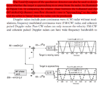
Hey I have just started work with radars. I read that incoming signal in case of Doppler radar is frequency shifted. On adding it to original signal we get doppler shift. But we dont do it directly. First we make I component ( by mixing incoming signal with LO signal) then Q signal by mixing orignal signal with phase shifted LO then do I + jQ. This I understand is to determine the direction of motion either towards or away from Radar. I am attaching excerpt from book. Can anyone please explain how this one signal in each waveform becomes zero?
 

Attachments

  • doubt_upload.png
    doubt_upload.png
    96.2 KB · Views: 133

Are you familiar with complex signal representation? I + jQ is just standard complex signal representation, where "I" is the real part (referred to as "in-phase") and "Q" is the imaginary part (referred to as "quadrature").

Once you follow the idea of complex signals, the role of Doppler is easy to see.
 

The concept of Doppler requires phase mixing the transmitted signal with received signal. The 90 deg phase shift puts the phase error in the middle of the linear range for greater accuracy. If received burst is delayed, then a delay line for Tx signal is used (analog or digital)

Another method uses zero crossing of incoming sine burst signal with synthesized sweep or CW of what was sent converted from sine to a sawtooth. Thus the velocity is the error frequency or slope of output sawtooth beat frequency. The direction of motion is the polarity of the mixed output sawtooth and the distance travelled is the accumulated phase error, which is done by a tracking PLL on FM burst and time delay represents distance between Tx and Rx sync sweep.
 

Hey thanks for the replies. I understand the concept of complex no.s euler forms etc but i am stuck with this really simple thing(i know this is stupid). Refer to the Image of the page i posted. Cos part goes directly into adder while -sin part is phase shifted by 90 degrees. So -sin(2*pi*f*t + 90) equals -cos(2*pi*f*t) no matter f is positive or negitive so upper expression is always 2 cos( 2* pi*f*t) and lower one is zero( irrespective of positive or negative doppler). But acc to the page this shouldnt be the case. Upper part will give signal if doppler is negitive while lower if its positive.
also i am aware of zero crossing detecting methods but i will be using stft to plot spectrogram . I just got stuck with this simple thing
 

Status
Not open for further replies.

Part and Inventory Search

Welcome to EDABoard.com

Sponsor

Back
Top