Continue to Site

Welcome to EDAboard.com

Welcome to our site! EDAboard.com is an international Electronics Discussion Forum focused on EDA software, circuits, schematics, books, theory, papers, asic, pld, 8051, DSP, Network, RF, Analog Design, PCB, Service Manuals... and a whole lot more! To participate you need to register. Registration is free. Click here to register now.

I could not establish a reliable RS485 communication!

Status
Not open for further replies.

seyyah

Advanced Member level 2
Joined
Oct 7, 2001
Messages
646
Helped
8
Reputation
16
Reaction score
8
Trophy points
1,298
Activity points
6,233
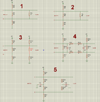
I have a master device in a machine room with two 7.5KW inverters and ac motors around. And a slave device 30 meters away from this room. Master and slave are on the same ground and communicates over RS485. Cable has parameters of C=3,3nF, L=60µH and Z= 135ohms. Cable is straight(flat cable) and unshielded and there is no way of changing it. Without inverters are running, communication is fine. But when inverters run, it malfunctions most of the time. I'm using standart SN75176 chips and transzorbs on both lines for protection. Used configurations are in the attachment and I also tried removing termination but not biasing on either sides. I've tried communication speeds of 2400bps to 19200 bps. The most reliable one was the 19200bps without any termination but with 470 ohm biasing and failed rarerly. Also slave side almost always gets the correct information but master side is the main side that is failing. I could not find a solution. May I take your suggestions please?Thanks
 

Attachments

  • rs485terminate&bias.png
    rs485terminate&bias.png
    24.4 KB · Views: 141
Last edited:

Obviously you are getting noise from your inverters onto your cable. WHY you (or whoever) used flat cable for a differential communications scheme is beyond me. You are supposed to use twisted pairs. The whole point of differential communications is so that any induced noise (like from an inverter) will be common-mode and will be cancelled at the receiver; you've managed to defeat that feature by using flat cable.

You DEFINITELY need to terminate your lines, although since it works with the inverters off, reflections are apparently not the main culprit here.

Have you looked at your signals with an oscilloscope? At least that way you can identify the enemy.
 
  • Like
Reactions: seyyah

    seyyah

    Points: 2
    Helpful Answer Positive Rating
Hi,

barry is absolutely right.
shielded twisted pairs is mandatory for RS485. The same is with termination.

*******
if you need to use the cables then: use a scope with frequency analyser.
Then install termination like it shoud be.
Then measure the signals.
Both signals in parallel. Then you can find out what to do.

There are common mode filters. low pass, or (adapted to you inverter frequency and/or baud rate) band pass filters.
Most probably you need a combination of them.
*******

maybe wireless (radio) data transmission or optical (fiber glass or POV) is a solution.

Klaus
 

I definitely agree on the cable with you but there is nothing I can do about it nor can i change the way it is, it is a long story. Anyway, I could only looked at the signals with a scope for a brief period of time but since I didn't have a differential probe and math function of the scope does not work well, I could not get a clear idea. But the signals were changing drastically while the inverters were running. I will inspect it with a scope in more detail later. I also thought of common mode filters but I could not find a suitable one. Can you offer some example parts and/or manufacturers? Thank you.
 

Try to isolate the ground.
 

The OP said the master and slave on the same ground, i meant to separate it.
 

RS485 does however have a finite (very finite) common mode range, +12 - 7 if I recall, so in a sense it is normally ground referenced.

An isolated transever might help as might a simple current balun, say a type 43 binocular core with as many turns of bifilar winding as you can fit.

My guess however is that an isolated transever will probably help matters greatly.

Regards, Dan.
 

It is difficult to apply isolation, it requires redesign of everything which takes a lot of time. Why do you think isolation will help? Main problem is the induced noise on the data lines and although the lines goes side by side, the balance is not well I think and/or there is a lot of common mode and diffferential mode noise. Will isolating the ground help it?
 

Hi,

First of all you have to measure. Both channels at the same time, but bot differential but on different channels. Then you can see if the induced signal is common mode or differential.
If they are mainly common mode, then a balun or common mode choke may help,
if differential, then you can try filters, independent on each channel or differentially.

Also with the scope you can see direction, waveform and magnitude of influenced signal.
.. and with that if it is out of common mode input voltage range.

Klaus
 

As already discussed by others, the problem is most likely common mode interference. RS485 based fieldbusses like PROFIBUS are using optical isolation for a good reason. If you don't provide isolation, a ground connection along with the twisted pair, either by the cable shield or a separate ground wire is mandatory. If you additionally use common mode chokes, the interferences can be usually brought under control.
 

As already discussed by others, the problem is most likely common mode interference. RS485 based fieldbusses like PROFIBUS are using optical isolation for a good reason. If you don't provide isolation, a ground connection along with the twisted pair, either by the cable shield or a separate ground wire is mandatory. If you additionally use common mode chokes, the interferences can be usually brought under control.

I may use four channels with the configuration of Ground - A - B - Ground. I think it should help. I think the inverters run at a frequency between 5-10KHz which coincides with the communications frequency that may be why when I increased the baud rate and it began to work. I'm trying to inspect the issue on the bench with two 100 meters cable, apart from each other and trying to inject noise via a signal generator. It is difficult to disrupt the communication on the bench, it works pretty well. I think I should use transformer or antenna like noise source to create a similar environment, so it is better to work on site for now...... The inverter will likely have some or all of the 3th, 5th and 7th harmonics dominantly. Also main frequency may coincide with the communication. What do you suggest for common mode filter? Can something like this https://www.mouser.com/ds/2/445/744834622-87466.pdf work?

- - - Updated - - -

I also want to add that in this situation, the termination affects adversly the communication, I think because of the voltage margin drops due to loading of termination.
 

Hi,

this is a high power line choke.

better look for signal chokes.
Maybe BOURNS DR331 series
or EPCOS B82794C0 series.

Klaus
 
  • Like
Reactions: seyyah

    seyyah

    Points: 2
    Helpful Answer Positive Rating
Hi Klaus,

I know and I don't want to use bulky solutions, but the signal chokes are genereally tuned to work in the upper MHz range. I don't know how much will they be effective in the kHz range.

Addition:
Hmm, epcos has some interesting parts thay may work I think, it is worth a try.

- - - Updated - - -

Hi Fvm, flat cable also carries gnd, do you think that any other gnd needed?
 

I know and I don't want to use bulky solutions, but the signal chokes are genereally tuned to work in the upper MHz range. I don't know how much will they be effective in the kHz range.
If a ground connection of sufficient cross section is carried along with the signal lines, there won't be much low frequency common mode interferences left. Problems may arise if the power circuit has missing or incorrect ground wiring and a large common mode voltage difference between both RS485 peers exists. In this case, it's in fact difficult to work without isolation. But you can still try with a larger toroid core of high µr ferrite, putting several turns of the RS485 cable (including ground) through it.
 
  • Like
Reactions: seyyah

    seyyah

    Points: 2
    Helpful Answer Positive Rating
I've inspected the signals a bit in more detail and saw that there are common mode noise and also differential mode noise especially at 16KHz. I've tried two common mode power type filters which were available at that moment and one of them greatly enhanced the communication and decreased the failures significantly. Then I tried to use series and parallel termination in combination with high value resistors like 1K in series and 10K in parallel on both sides. And that configuration reduced communication error rate to zero and worked in all conditions with a speed limit of 19200bps.
 

Status
Not open for further replies.

Part and Inventory Search

Welcome to EDABoard.com

Sponsor

Back
Top