Continue to Site

Welcome to EDAboard.com

Welcome to our site! EDAboard.com is an international Electronics Discussion Forum focused on EDA software, circuits, schematics, books, theory, papers, asic, pld, 8051, DSP, Network, RF, Analog Design, PCB, Service Manuals... and a whole lot more! To participate you need to register. Registration is free. Click here to register now.

Rectifier ADS co-simulation Layout+schematic

Status
Not open for further replies.

simazafrani

Newbie level 6
Joined
Feb 24, 2009
Messages
12
Helped
0
Reputation
0
Reaction score
0
Trophy points
1,281
Activity points
1,368
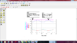
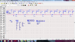
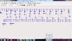
Hi...i'm working on rectifier circuit using ADS....i got a good results in schematic simulation..however when i convert the circuit to layout...my result decreased about 1V and fluctuated/ have a big ripple (+-4V ripple). I would like to ask any suggestion to improve/optimize my result so that i could at least reduced the fluctuated on the output result.:thinker:

attached here the circuit n result from both simulation
 

Attachments

  • output.png
    output.png
    136.3 KB · Views: 121
  • Villard7Schematic.png
    Villard7Schematic.png
    159.1 KB · Views: 122
  • Villard7layoutSchematic.png
    Villard7layoutSchematic.png
    154.4 KB · Views: 121

Status
Not open for further replies.

Part and Inventory Search

Welcome to EDABoard.com

Sponsor

Back
Top