Continue to Site

Welcome to EDAboard.com

Welcome to our site! EDAboard.com is an international Electronics Discussion Forum focused on EDA software, circuits, schematics, books, theory, papers, asic, pld, 8051, DSP, Network, RF, Analog Design, PCB, Service Manuals... and a whole lot more! To participate you need to register. Registration is free. Click here to register now.

[SOLVED] ICSP in dspic30f2010

Status
Not open for further replies.

ismu

Full Member level 2
Joined
May 12, 2009
Messages
145
Helped
1
Reputation
2
Reaction score
1
Trophy points
1,298
Location
nil
Activity points
2,340
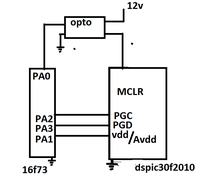
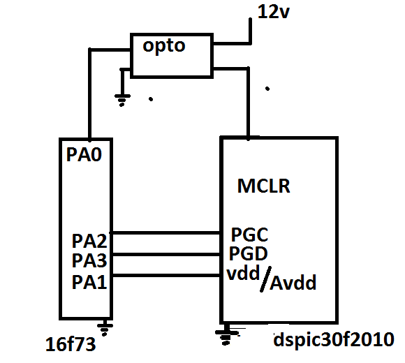
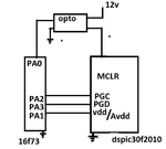
i am trying to program/erase dsPIC30F2010 using ICSP protocol [App note :DS70102J ] by using normal 16F73 . see diagram and code of 16f73.
Am getting the pulses currectly , but chip erase is not working , like this ,itried chip program ,also not working . pls verify bellow code.
ICSP algoritham based on microchip App note :DS70102J

//////////////////////////////////////////////////////////////////////////


///////////////////////////////////////////////////////////////////////////

Code C - [expand]
1
2
3
4
5
6
7
8
9
10
11
12
13
14
15
16
17
18
19
20
21
22
23
24
25
26
27
28
29
30
31
32
33
34
35
36
37
38
39
40
41
42
43
44
45
46
47
48
49
50
51
52
53
54
55
56
57
58
59
60
61
62
63
64
65
66
67
68
69
70
71
72
73
74
75
76
77
78
79
80
81
82
83
84
85
86
87
88
89
90
91
92
93
94
95
96
97
98
99
100
101
102
103
104
105
106
107
108
109
110
111
112
113
114
115
116
117
118
119
120
121
122
123
124
void main()
{
TRISB=0b00000001;
TRISA=0b00000000;
ADCON1=0b00000110;
TRISC=0b00000000;
VDD=1;
for(;;)
{
stop();     
  if(!PROGRAM)    ////switch is active
  {
   start_ICSP();        
   Bulk_Erase();
   stop();      
  }
}
}
 
 
///////////////////////////////////////////////////////////////////
void stop(void)
{
  DAT=0;
  CLK=0;    
  MCLR=0;
  __delay_ms(100);
}
////////////////////////////
void start_ICSP(void)
{
 stop();
__delay_us(1);   ///100ns is min
MCLR=1;
__delay_ms(30);   ///25ms is min
 
dspic_send_24_bits(0,0);
__delay_ms(1);
dspic_send_24_bits(0,0);
__delay_ms(1);
dspic_send_24_bits(0,0);
__delay_ms(1);
dspic_send_24_bits(0,0);
__delay_ms(1);
MCLR=0;
__delay_us(1);   ///4us is min
MCLR=1;
} 
/////////////////////////////
 
void Bulk_Erase(void)
{
dspic_send_24_bits(0,0);
dspic_send_24_bits(0,0x040100);
dspic_send_24_bits(0,0);
 
dspic_send_24_bits(0,0x2407FA);
dspic_send_24_bits(0,0x883B0A);
 
dspic_send_24_bits(0,0x200558);
dspic_send_24_bits(0,0x883B38);
dspic_send_24_bits(0,0x200AA9);
dspic_send_24_bits(0,0x883B39);
 
dspic_send_24_bits(0,0xA8E761);
dspic_send_24_bits(0,0x0);
__delay_ms(2);
dspic_send_24_bits(0,0x0);
dspic_send_24_bits(0,0xA9E761);
dspic_send_24_bits(0,0x0);
__delay_ms(2);
}
///////////////////////////////
 
 
///////////////////////////////////////////////////////////////////
void dspic_send_24_bits(unsigned char SIX_CMD_or_REGOUT, unsigned long data)
{
    unsigned char i,cmd_temp;
    cmd_temp=cmd;   
    for(i=0;i<4;i++)
    {
        if(cmd&1)
         DAT=1;
        else
         DAT=0;
        cmd>>=1;
 
 
        __delay_us(5);
        CLK=1;
        __delay_us(5);
        CLK=0;
    }
    
    
     for(i=0;i<24;i++)
       {
      if(cmd_temp==0)   
        {
        TRISA=0b00000000;       
        if(data&1)
         DAT=1;
        else
         DAT=0;
        data>>=1;
        }
      else if(cmd_temp==1&&i>7)
        {
        TRISA=0b00001000;
        }   
        
    __delay_us(5);
        CLK=1;
        __delay_us(5);
        CLK=0;
    }
TRISA=0b00000000;  
}


Attachments

  • Untitledw.png
    Untitledw.png
    14.5 KB · Views: 85
Last edited by a moderator:

I didn t check your codes
and I can t because I don t know the algorith for programming dspic30f2010.

I had made 16f877 programmer,
i ran into these problems;
Vdd supply voltage i used was not sufficent,
also Vpp is very important,
maybe for your circuit 12V is not enough,
for 16f i used 13~13,5V,
and first i couldnt erase code protected chip
then i added 10uF elec cap to Vdd GND lines
problem disappered.

And maybe you need to use Vdd or Vpp first programming
when you getting into programming mode.
And for Vdd of dspic you need to supply more than 20mA that 16f73 PA1 can supply.
I think you didnt forget to use same GND for dspic and 16f73
 

i tried to program 16F676 and 16F73/72/873 by using same setup , it was woking fine[vpp=13v] , i tried with 13V vpp for dspic also ,but for dspic it is not working ,

how can i ensure it enterd in ISCP mode?

what is vdd/vpp first programing?

PA1 maximum limit is 20mA

gnd for 73 and dspic are same.
 

Vdd/Vpp first programming means;
you have two option,
one of this is
you may first apply Vdd 5V and then
apply Vpp 13V, this is Vdd first method,
the other one is
you first apply Vpp 13V and then
apply Vdd 5V, this is Vpp fisrt method.

Entering the icsp programming mode
(i have look at the dspic 30f2010 programming specification
i think you are using it know
https://ww1.microchip.com/downloads/en/DeviceDoc/70102J.pdf page ~37)
(as i can understand dspic30f2010 also enhanced icsp mode)
the PGD and PGC held in low
then apply Vpp wait at least 25ms then execute 2-4 nop
(nop is the SIX instruction code table 11-1 cpu control codes in icsp mode)
etc.

You know this a little bit a hard work,
even if I had done this but i had t
also i can t be able to solve your problem,
i only tried to help from the easy part from the hardware,
you have to cautiously follow all the steps in the programming specification,
i can not check it, i think also anyone can not check it.

For the Vdd
dont use PA1 directly
use a circuit swithed from PA1
and can supply more than 20mA to Vdd of dspic
 
  • Like
Reactions: ismu

    ismu

    Points: 2
    Helpful Answer Positive Rating
Vdd/Vpp first programming means;
you have two option,
one of this is
you may first apply Vdd 5V and then
apply Vpp 13V, this is Vdd first method,
the other one is
you first apply Vpp 13V and then
apply Vdd 5V, this is Vpp fisrt method.

Entering the icsp programming mode
(i have look at the dspic 30f2010 programming specification
i think you are using it know
https://ww1.microchip.com/downloads/en/DeviceDoc/70102J.pdf page ~37)
(as i can understand dspic30f2010 also enhanced icsp mode)
the PGD and PGC held in low
then apply Vpp wait at least 25ms then execute 2-4 nop
(nop is the SIX instruction code table 11-1 cpu control codes in icsp mode)
etc.

You know this a little bit a hard work,
even if I had done this but i had t
also i can t be able to solve your problem,
i only tried to help from the easy part from the hardware,
you have to cautiously follow all the steps in the programming specification,
i can not check it, i think also anyone can not check it.

For the Vdd
dont use PA1 directly
use a circuit swithed from PA1
and can supply more than 20mA to Vdd of dspic


Hi now am triying ICSP mode instead of enhanced , ie : Vdd first methode . i did one change means i am directly connected VDD=5V from regulator out put ,[without contrloling] so we remove 20mA problem .stil it is not working . can u simply check with erase code only , check whether it is happening or not? :(
 

hi all

problem solved , now working fine , thanks all
 

Status
Not open for further replies.

Similar threads

Part and Inventory Search

Welcome to EDABoard.com

Sponsor

Back
Top