Continue to Site

Welcome to EDAboard.com

Welcome to our site! EDAboard.com is an international Electronics Discussion Forum focused on EDA software, circuits, schematics, books, theory, papers, asic, pld, 8051, DSP, Network, RF, Analog Design, PCB, Service Manuals... and a whole lot more! To participate you need to register. Registration is free. Click here to register now.

Step up voltage booster converter.

Status
Not open for further replies.

cybertron

Member level 3
Joined
Jul 9, 2004
Messages
61
Helped
0
Reputation
0
Reaction score
0
Trophy points
1,286
Location
USA
Activity points
609
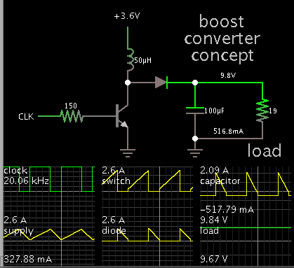
I'm looking to boost a voltage of 3.6V to 9.5V with a maximum current out of 0 to 0.5A
for battery powered device.

Would like to fine an already built unit if anyone knows of one.
Or a working circuit schematic that someone done or knows of a circuit I can use

I done a search on Google. But? Wasn't able to fine what I needed.
Maybe someone on here know's of such a module that would work for me.
 

A boost converter will do the job. This simulation illustrates the concept.

1293178300_1409362522.png


Notice your 3.6V supply must be able to provide a few A. (Watts out cannot be greater than watts in.)

Not shown is the feedback and control circuitry. This is needed to regulate the output voltage.

Perhaps the complete works is manufactured in a single IC. Somebody with more experience might know one way or the other.
 

I found this circuit doing a google search.

Its input is 3.3V and output is 9V would this work.its a single chip all in one circuit booster.
I need 3.6V in and 9V out.

Can someone on here simulate this circuit to see if the spec apply
for what I need.you can find the datasheet.Enclosed
 

Attachments

  • BOOSTER  STEP-UP  VOLTAGE REG.PNG
    BOOSTER STEP-UP VOLTAGE REG.PNG
    41.2 KB · Views: 137
  • lmr62014 step up boost converter datasheet.pdf
    1,020.7 KB · Views: 85

You are on the right track, although you need to be willing to reduce your specification for V and A output.

Looking at Fig. 22...
The graphs show that (for supply input 3.6V), the device will yield about 450mA at 8V.
At 9V it looks like 350 mA.

If you want greater current, there might be other IC's in this family (probably more expensive too).
 

Hi

I found another step-up boost on LT website.Would this one work for my requirements.

And how do I get the 9.5 VOLTS on the output with 3.6V on the input. With R2 at 113K what would
R1 be. I can't do the formula to calculate for R1. CAN YOU HELP?

PLEASE. Which application circuit do I use for my circuit in the datasheet.
 

Attachments

  • LTC3124f Datasheet.pdf
    644.6 KB · Views: 90

Hi

I found another step-up boost on LT website.Would this one work for my requirements.

And how do I get the 9.5 VOLTS on the output with 3.6V on the input. With R2 at 113K what would
R1 be. I can't do the formula to calculate for R1. CAN YOU HELP?
R1 has 1.2V across it. You want the output to be 9.5V so R2 has 9.5V - 1.2V = 8.3V across it. Then Use Ohm's Law to simply calculate the current in R1 and R2. Use Ohm's Law again to calculate the value of R1. The same as calculating R2 for an LM317 except its R1 must be 120 ohms.

The last schematic in the datasheet is similar to your voltages except the values of R1 and R2.
 

Hi,

Audioguru already told how to calculate R1. This is the way i often use too, because it it the more "visual" way. It is easy to remember and it simply uses ohm´s law.

Now to the mathematical solution:

the formula in the datasheet is:

Vout = 1.2V * ( 1 + ( R1 / R2 ))

solved for R1:

R1 = (V_out - 1.2V) * R2 / 1.2


Hope that helps.
Klaus

**********
PS:

Two small points of criticism on the LT´s datasheet, that makes hobbyist´s life harder than needed:
1) they recommend 113k as R2. Only a few of us will have a 113k resistor in stock. I can´t find a benefit of 113k compared to a standard 100k, therefore i´d recommend a 100k as R2
2) the formula is solved for V_out. No developer would go this way. V_out is given by the application, and R2 is recommended in datasheet. Everyboby is looking for R1. The printed formula in datasheet should be: R1 = (V_out - 1.2V) * R2 / 1.2
Besides this LT is makes high quality devices, very detailed datasheets and very detailed application notes.
 

Hi


Thanks? The why you explained klausST made me understand it more. Then the way Audioguru explained it.
even doe it the same solution. Tell me if I got it right. R1= 9.5V out -1.2=8.3 X 100,000=830,000 /1.2 =691.66K or 692K for R1

Tell me if this is correct? Can I use a 692K if available. Thanks AG and Klaus
 

Hi,

If you use 100k for R2, then yor calculation is right.


Klaus
 

Status
Not open for further replies.

Part and Inventory Search

Welcome to EDABoard.com

Sponsor

Back
Top