Continue to Site

Welcome to EDAboard.com

Welcome to our site! EDAboard.com is an international Electronics Discussion Forum focused on EDA software, circuits, schematics, books, theory, papers, asic, pld, 8051, DSP, Network, RF, Analog Design, PCB, Service Manuals... and a whole lot more! To participate you need to register. Registration is free. Click here to register now.

[SOLVED] MOSFET Switching problem

Status
Not open for further replies.

amayilsamy

Advanced Member level 1
Joined
Feb 5, 2013
Messages
420
Helped
38
Reputation
76
Reaction score
34
Trophy points
1,308
Location
Chennai,India
Activity points
3,370
Hi...

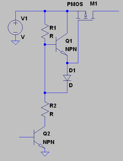
I do with mosfet switch with IRF9530.

But It was not working properly. The prolem my switch on time 100 us for every second.

Here i attached schematic and output wave form.
sw.JPG

How to solve this .

Thanks
 

Your circuit has several issues.

Worst of all, 35 V gate voltage will immediately kill the MOSFET. You need a voltage limiting means for the gate voltage.

Secondly, the relative large load resistor R1 will only slowly discharge the gate capacitance. For fast switching a lower resistance or preferably a push-pull driver circuit is necesary.

Finally, the load capacitance may ruin the intended switch-off speed. What's the load?
 

Hi,

As FvM mentioned you have to lower the gate resistor. maybe use a 1k5 Ohms resistor.
From collector of BJT to gate of FET use a 3k resistor.

This improves switch off time of your FET.

+++++
But i´m not sure if this is the solution to your problem, because with 5k ohms load you may always see a slow switching off with your scope. This may be caused by stray capacitance in your output circuit.
To improve on this you may use a low ohmic load.

**********
BTW. there are ready to use one part solutions for you. They are called "high side switches". Some of them have thermal, overcurrent, short circuit and overvoltage protection inside.

Klaus
 

Intelligent highside switches will basically work, but are slow switching to reduce EMI.

Please think about this possible driver topology


In case of variable input voltage, a voltage limiting Z-diode across PMOS source drain can be useful.
 

Thanks FvM, I Check this and update..

****************************

I Constructed the above cicuit . Again I'm same result.

Q1,Q2=BC547
R1,R2=10K
M1=IRF95305
D1=1N4007

- - - Updated - - -

I Constructed the above cicuit . Again I'm same result.

Q1,Q2=BC547
R1,R2=10K
M1=IRF95305
D1=1N4007
 
Last edited:

Simulation or measurement?

1N4007 is somewhat slow, 1N4148 would be better. But probably not the dominant problem. You can try to reduce the resistor values to the minimum according to acceptable power dissipation, e.g 1 - 2 k. Also monitor the gate voltage waveform. It may be still a load capacitance problem.
 

It's measurement.

I replaced with R1&R2 is 1K, D1 is 1n5819. Again I'm getting same results.

The MOSFET Gate voltage form Inversion of above output wave form.

And one more thing output voltage goes to 13.5V . I need switch output voltage 35V
 

Hi,

It seems like you have 10...20nF capacitance at the output in parallel to the 5k load.
Can this be a log cable or other circuitry?

Klaus
 

Hi,

It seems like you have 10...20nF capacitance at the output in parallel to the 5k load.
Can this be a log cable or other circuitry?

Klaus

I already did this , it is take mosfet discharging time + capacitor discharging time..
 

And one more thing output voltage goes to 13.5V .
Makes no sense. Apparently the real circuit is different from the schematic.

- - - Updated - - -

I checked the circuit in a simulation with a similar PMOS transistor (Si7113) which has probably a higher output capacitance. As expectable the output rises to full 35 V, the fall time (t90_10) with 5k load is about 10 µs, solely caused by transistor output capacitance. Any additional load impedance will of course increase it.

If you want lower fall time and/or have considerable load capacitance, you should think about a discharge switch.

Below are the LTSpice files.
 

Attachments

  • PMOS-switch.zip
    962 bytes · Views: 45

Finally I did this making some changes in that.

IRF9530 replaced with n-channel mosfet IRFZ44N and R1 value. 3K resistor

Thanks to all..
 

Status
Not open for further replies.

Similar threads

Part and Inventory Search

Welcome to EDABoard.com

Sponsor

Back
Top