Continue to Site

Welcome to EDAboard.com

Welcome to our site! EDAboard.com is an international Electronics Discussion Forum focused on EDA software, circuits, schematics, books, theory, papers, asic, pld, 8051, DSP, Network, RF, Analog Design, PCB, Service Manuals... and a whole lot more! To participate you need to register. Registration is free. Click here to register now.

[SOLVED] INT0 of uC enabling how ?

Status
Not open for further replies.

Raady Here

Full Member level 5
Joined
Jun 8, 2013
Messages
242
Helped
26
Reputation
52
Reaction score
26
Trophy points
28
Location
India
Activity points
1,571
PIC30F5011, MPlab8.8

I sending a digital signal of frequnecy 400khz(checked with oscilloscope) to port RF6.
I am trying to measure frequency of a signal and trying to configure INT0
when ever i get a INT0 i am incrementing a varioable "freq_counter "

in timer1 for every 10ms i am calculating frequency and clearing "freq_counter"

I dont read any thing "freq_counter"

had i done initilization of INTO correctly ?

Code:
void INIT_INT(void)
{
	D_INT0_x                    = 1; // setting input, INT0 (RF6 )
	INTCON2bits.INT0EP 	= 1; 	// Interrupt on negative edge
	IEC0bits.INT0IE 	        = 1;    //Enable INT0 Interrupt Service Routine
	IPC0bits.INT0IP 	        = 7;
	IFS0bits.INT0IF		= 0;	// Clear INT0IF 
}
void __attribute__((auto_psv,__interrupt__)) _INT0Interrupt(void)
{
	freq_counter++;
	IFS0bits.INT0IF		= 0;
}

int main()
{
	INIT_Peripheral();
	while(1)
	{	
		
		printf("freq : %d\n",freq_counter);
	}
}

void INIT_TIMER(void)
{
	T1CON    		= 0;				// Disable Timer1 for Clock and Reset.
	
	TMR1 		= 0x0000;			// Clear RTC Timer Register.
	PR1    		= 10000;			// Set Timer1 period register for 10ms
	T1CONbits.TCKPS	= 1;				// Set Timer1 Input Clock Prescale Select bits (1:8)
	
	IFS0bits.T1IF  	= 0;				// Reset Timer 1 interrupt flag
	IPC0bits.T1IP  	= 7;				// Set Timer1 interrupt priority level to 7
	IEC0bits.T1IE  	= 1;				// Enable Interrrupt w.r.t Timer 1
	
	T1CONbits.TON  	= 1;				// Enable Timer1
}


/* Timer Interrupt */
void __attribute__((__interrupt__,no_auto_psv)) _T1Interrupt(void)
{
	IFS0bits.T1IF = 0; 						//Clear Timer1 interrupt flag
	timin = (float)0.01/freq_counter;
	freq_counter = 0;
	Flag.TimerDelay_10ms = 1;
}
 

I tend to use "Interrupt on change" for such applications but external interrupt should work
however, I cannot see anything obvious wrong with the code

what are the low/high voltage levels of your signal? are getting asufficent change to give an edge to trigger an interrupt?
 

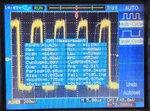
the reading that i see on oscilloscope
pk-pk : 13.2v
amps : 12.4 v
max : 13.2 v
min : -400mv
avg : 6.00 v
RMS : 8.00 v
Cyc avg 4.00 v
cyc rms 8.00 v
freq : 19.08 khz - 25.83 khz (varying)
rise : 979 ns
fall : 210 ns

- - - Updated - - -

disortion is high what can i do ?
 

the first thing is to check that the INT0 code is working
can you replace the signal on RF6 with a switch that will input a low/high signal
and comment out the statement
Code:
freq_counter = 0;
operate the switch and freq_counter should change

could you use a schmitt trigger device to 'tidy' up the signal?
 

I tried adding a capacitor at the measurement of output and
reading were bit varied though, noise was bit lesser.
IMG_29161.jpg
 

the peak to peak voltage is 1.62volts which is probably insufficent to give an interrupt??
check the device datasheet
 

i had given common supply to both my controller and external circuit with a regulated power supply than a 5v 1a adopter.
Now I had pk-pk as 2.02 V, with out capacitor connected to take measurement.

If that pk - pk voltage is not enogh to drive interrupt, is there any other way so that i can measure the frequency with lower pk - pk voltages.**broken link removed**

looking at tablle 1.1 of the data sheet
https://www.microchip.com/wwwproducts/Devices.aspx?product=dsPIC30F5011

pin RF6 is a schmitt trigger input

then assuming I am reading table 23.8 the data sheet correctly - for a schmitt trigger buffer
low is Vss to .2Vdd
high is 0.8Vdd to Vdd

assuming Vdd is 5volts low is 1volt and high is 4volts - looks like you need to amplify the signal
 

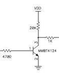
perhaps a simple NPN transistor circuit would convert you signal to a suitable level for the dsPIC30 input, e.g.
NPNcircuit.jpg
 

I have added the circuit that you mentioned, distortion has reduced and its still not able to tigger the input as it still doesnt reach above 1v.SCOPE.gif
 

probably need a more sophisticated amplifier circuit
put a question on the Analogue design forum?
 

Status
Not open for further replies.

Similar threads

Part and Inventory Search

Welcome to EDABoard.com

Sponsor

Back
Top