Continue to Site

Welcome to EDAboard.com

Welcome to our site! EDAboard.com is an international Electronics Discussion Forum focused on EDA software, circuits, schematics, books, theory, papers, asic, pld, 8051, DSP, Network, RF, Analog Design, PCB, Service Manuals... and a whole lot more! To participate you need to register. Registration is free. Click here to register now.

12 to 220 modified inverter

Status
Not open for further replies.

abdoalghareeb

Member level 5
Joined
Feb 5, 2010
Messages
83
Helped
1
Reputation
2
Reaction score
1
Trophy points
1,288
Activity points
1,974
I have built my 12 to 220 modified inverter (1000 watt).
I use ATMEGA8 and IRF3205 in my design.
I am sure about 220V and 50Hz on output.
My design almost look like this.
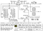
500W-Modified-Sine-Wave-Inverter-ElectroSuite.jpg
In addition to feedback signal.
My problem is : this inverter Destroyed my three home fans (its driver board use triacs).
table_fan.jpg
Is there any way to solve this problem?
 

220 modified

This sounds as though your inverter is modified sinewave, correct? A waveform whose appearance is halfway between square wave and sinewave?

The problem might be a matter of how high your peak voltage goes, in order to match the RMS power of a sinewave.

A 220V sine has a peak amplitude of 220 x √2, or 311V. Does your inverter put out a greater amplitude?
 

The speed control circuit using triacs in the fan expects a smooth sinewave, not the abrupt pulses of a modified sinewave.
The 10V transformer does not produce enough output voltage for the average voltage to be 220AC. The peak voltage of 220VAC is 311V but the 10V transformer produces a peak voltage of less than 12/10V x 220V= 264V. Then the average output voltage is only 187VAC.
 

Status
Not open for further replies.

Part and Inventory Search

Welcome to EDABoard.com

Sponsor

Back
Top